Introduction
What is Ashlar-Vellum Kinetics?
Ashlar-Vellum Kinetics is a 3D motion simulation, scene building, sharing, rendering, and animation application. It supports importing native and standard 3D file formats to build 3D scenes that can than be exported into many file formats.
Kinetics was designed to be very easy to use, with a short learning curve, without limiting design capabilities.
Kinetics, new interface is based on selecting the workbench from which to work. Upon selecting any workbench the Workbench Tasks, Properties, Task, and Library Panels in the interface will be changed to display the defaults of that selected workbench.
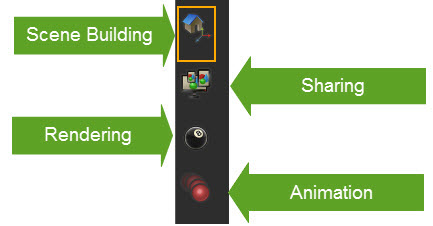
On the left hand side of Kinetics interface, the user can find six icons. Each icon refers to a workbench in Kinetics. The icons will be active according to available license(s).
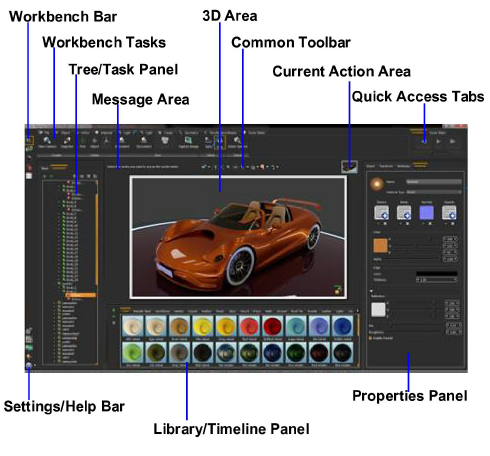
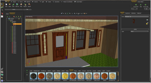
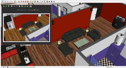
As shown in the above image, the application interface has different sections.
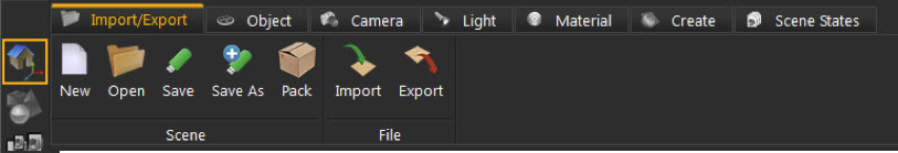
From the Workbench Bar select the workbench to use. The available workbenches are as listed below, and each application and its corresponding functionalities are described in separate sections.
Different workbenches in Kinetics provide different tasks. The Workbench Tasks, the Properties, Task, Library Panels all change according to the selected workbench. For example the Scene Building Workbench includes the tasks shown in the image below.
Each task within a workbench will change the Kinetics interface to help perform the task more easily. For example selecting the File Task shows the Material Library in the Library Panel. Changing to the Object Task shows the Object Library instead.
Some tasks, like the Camera Task in the Scene Building workbench, have no effect on the Library Panel. This helps advanced users flow between workbenches.
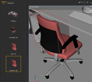
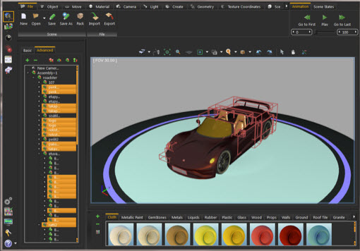
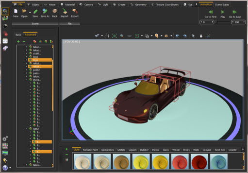
This section usually displays the Object Tree, with its two formats; Basic and Advanced.
In the Basic Tab, the tree shows the images for the selected geometry all the way up to its top parent.
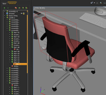
The Advanced Tab shows the assembly structure of all assemblies in the scene. Kinetics maintains the assembly structure of imported 3D geometry, in the Object Tree. Maintaining the assembly structure enhances the usability of 3D models, as it allows parts/assemblies to be moved, materials reassigned, and geometries to hide/show easily.
Click the top level View menu, then select Object Tree to display the tree structure of the 3D scene.
By default, picking selects a 3D Geom ( ), which is the “leaf level” in the assembly tree. Then navigate up the tree in one of the following ways:
• Double clicking, selects the top level assembly of the tree.
• Holding SHIFT while double clicking moves up the tree one level at a time. So repeating SHIFT + double click eventually will reach the top level assembly of the tree.
• Select the desired branch directly from the tree.
Holding the CTRL key allows for selecting multiple geometries. All drag and drop functions can then be applied to the multiple selected geometries.
Sometimes this panel displays application specific functions, like Render Settings, when the Rendering Workbench is selected.
Regardless of the selected workbench, in Kinetics, this toolbar is displayed on top of the 3D Area. It enables different functions to set the view of the 3D Area, as described below, starting from left to right.
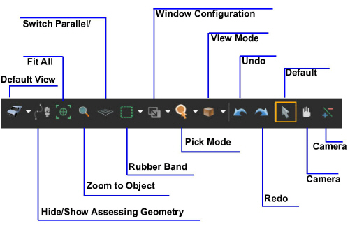
This function sets the view orientation for the active viewport to one of the default view orientations.
|
Button |
Effect |
Short Cut |
|---|---|---|
|
|
Select one of the default view orientations, ISO, Top, Bottom, Front, Back, Right or Left |
CTRL+7 |
|
|
Top View |
CTRL+1 |
|
|
Bottom View |
CTRL+2 |
|
|
Front View |
CTRL+3 |
|
|
Back View |
CTRL+4 |
|
|
Right View |
CTRL+5 |
|
|
Left View |
CTRL+6 |
Assessing geometry in Kinetics includes paths, cameras, and lights. This function hides or shows any of the geometry in the scene at any time.
This function automatically updates the camera to fit all geometry in the scene within the active view area.
This function updates the camera in the active viewport by zooming to the selected object. If this button is pressed without selecting an object, a message will be displayed on top of the 3D area asking for a selection to be made.
Switch between Parallel and Perspective View
This switches the camera between perspective and parallel modes, in the active viewport. For engineers used to parallel mode, this option is particularly helpful.
This function changes the selection mode in the 3D area and has three options:
|
Changes the selection icon to a square band and allows selecting more than one geometry in the 3D area. |
|
This icon will show a ‘+’ sign inside the square band. Select more geometry in a different section of the 3D scene and add it to the first selection, without losing the previous selection, as shown in the image below. |
|
Remove from Current Selection |
A ‘-‘ sign appears in the band, allowing the removal of geometry from the selection, without losing the previous selections. In the image shown below, some geometry was removed from the selections made in the previous two options. |
This button selects the number of views in the 3D area including those shown here:
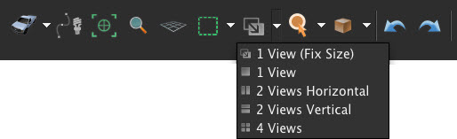
Views can also be displayed by pulling the right and bottom edges of the 3D area.
When starting Kinetics the default picking mode is enabled. Picking returns two values; a location and a normal direction. Change the picking mode to one of the following as needed.
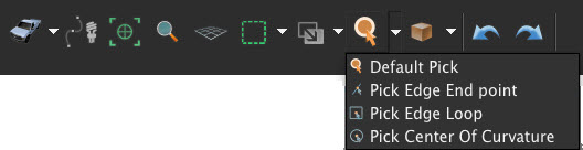
The picking modes in Kinetics are:
|
This mode picks a point in the model. The location and the normal direction at that point are returned. The geometry at the picked location will be selected in the Object Tree, and its bounding box will be displayed in the 3D area. |
|
|---|---|
|
This mode highlights the edge closest to the selected point, and the returned normal will be tangent of the curve at the closest end. In the image shown below, when selecting the door’s edge, the selection point is closer to the bottom side of the door. Thus the returned normal is pointing upwards. In this mode the Generate Edges progress bar appears, and the edges of the models in the scene are shown. |
|
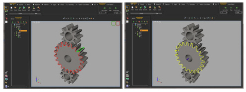
This picking mode is useful for selecting the center of a loop. Upon selecting this mode the models’ edges are generated. If two loops are close to the selected point, both of them will be highlighted, one in green and the other with red. Two loop icons appear on the upper right side of the 3D area, allowing the desired one to be selected. In the left image below, to get the center of the gear, select the red loop icon. After selecting the red loop icon, the normal at the center of the gear is displayed, as shown in the right image. This can be helpful, for example, in picking the center of rotation in a Wheel animation. |
|
With this mode picking a curve highlights the curve, and displays its center normal, as shown in the image below. |
The default view in Kinetics is the Solid View. It displays models as solids with the edges hidden. Select any of the following view modes in Kinetics.
|
Button |
Effect |
Short Cut |
|---|---|---|
|
|
X Ray View |
ALT+1 |
|
|
Edge Only View |
ALT+2 |
|
|
Solid Illustration View |
ALT+3 |
|
|
Solid View |
ALT+4 |
|
|
Real Time |
F4 |
|
Gives an x-ray effect to the models in the scene. |
|
|---|---|
|
Displays only the edges of the models in the scene. |
|
|
Displays models in solid view, with their edges illustrated. |
|
|
Displays models in shaded solid view. |
|
|
Starts real-time rendering for the 3D models in the scene |
Undo / Redo
These two function buttons will undo or redo performed actions respectively in Kinetics.
Default Behavior
This function sets Kinetics to default behavior described in the following table.
|
Navigation |
Mouse Button |
|---|---|
|
Middle mouse button |
|
|
Left mouse button |
|
|
Right mouse button |
This function changes the behavior of the left mouse button to Pan.
This function changes the behavior of the left mouse button to Zoom.
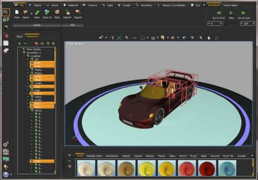
This panel displays a different library, depending on the selected workbench / task combination. For example at the Scene Building Workbench, the Materials Library is shown by default. The Object Task from the Scene Building Workbench, the Basic Shapes Library is displayed instead. In the Animation Workbench the timeline is displayed instead.
In any library there are three buttons, as shown in the Material Library image below.
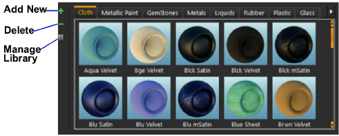
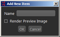
Clicking this button adds a new item to the corresponding library. In the Basic Shapes Library, for example, clicking this button will display the Add New Item dialog box. Input the name for the new item, and choose whether or not to render its preview image.
This button deletes the selected item from the library.
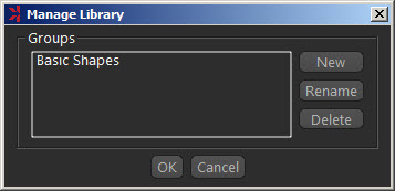
Clicking this button displays the Manage Library dialog, where new library(s) are added, and existing ones renamed or deleted.
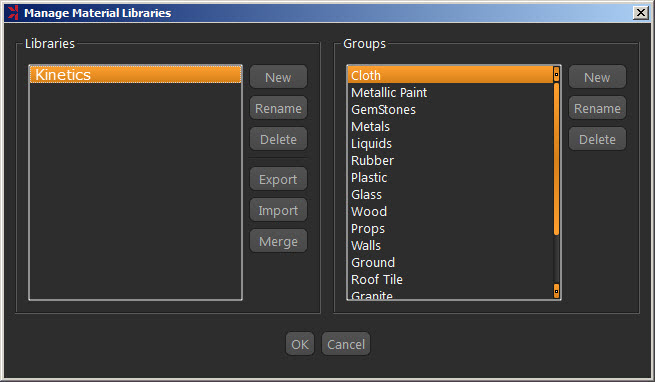
The Manage Material Libraries dialog has more options. Kinetics, by default, comes with the Kinetics Materials Library that has different groups and materials types. In this dialog different material libraries are exported, imported, or merged. Material libraries are exported in the (*.mlb) file format, and the packed libraries to import should have the same file extension.
With any workbench, when geometry is selected in the 3D area, this panel displays four tabs describing the selected geometry as described here
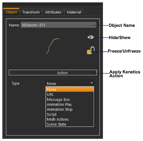
This tab changes the selected object Name property. Other object properties that can be set in this tab include:
|
Hide/Show |
By clicking this icon hide/show the selected object in the 3D area. These two functions are available in the Object tab of the Scene Building Workbench. |
|---|---|
|
Freeze/UnFreeze |
Freezing the selected object will lock its position and orientation in the 3D area. All transformation functions will NOT be applicable to it, until this icon is clicked again to unfreeze it. This function is available in the Object tab of the Scene Building Workbench. |
|
Apply Actions |
In this combination box, select any of Kinetics actions to apply to the selected object. Applied actions are exported to 3D PDF files, as well as HTML (Web GL). |
Kinetics supports a number of predefined actions that can be executed upon clicking a 3D model, or clicking templates’ elements. Advanced users can write their own script to define new actions. Kinetics actions can be executed in 3D PDF, and HTML files.
|
Action |
Effect |
|---|---|
|
URL |
Links 3D geometry or template element with the entered web address that will be opened On Click. |
|
Message Box |
Displays a message box upon clicking 3D geometry or template element. Enter the message and its title. |
|
Animation Play |
Plays a scene’s animation upon clicking 3D geometry or template element. One animation is supported for a scene. |
|
Animation Stop |
Stops playing a scene’s animation upon clicking 3D geometry or template element. |
|
Script |
Enables users to write their own script to be executed upon clicking 3D geometry or Template element. |
|
Scene State |
Executes a scene state upon clicking 3D geometry or template element. Scene states can be selected by name or index. |
|
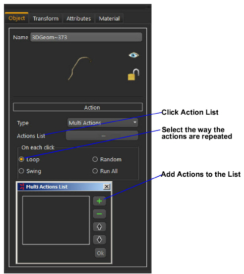
Multi Actions |
Executes a number of actions upon clicking 3D geometry or template element. |
If the Multi Actions option is selected, clicking the Actions List button opens the Multi Actions List dialog. Click the ‘+’ button and enter a list of actions of different types. The order of these actions is changed using the up and down arrows. These actions are executed upon clicking the selected 3D geometry, or applied in 3D PDF templates.
Supported ways of applying the actions list are:
|
Loop |
Runs the actions’ list in order upon a mouse click, then begins again. That is action_1, 2,3 …, then 1, 2, 3. |
|---|---|
|
Swing |
Runs the actions’ list in order upon click, then runs it backwards. That is action_1, 2,3 …, then 3, 2, 1. |
|
Random |
Runs the actions’ list randomly upon click. |
|
Run All |
Runs the actions’ list in order one time upon click. |
In this tab the location of the selected object and its pivot are known, as well as changed with precise values. Also uniform or non-uniform scaling can be done for the object around its center.
Both the object and its pivot have global, and local locations and orientations. The global location is the location of the object’s center relative to the world’s coordinate system. The local location changes according to the transforms performed on the object, relative to its parent.
This tab defines the attributes attached to the selected geometry in the 3D scene. These attributes are exported to 3D PDF files, when the Export Object Attributes option in the Advanced tab of PDF Settings dialog is checked. This helps designers communicate BIM and meta data.
This tab changes the Name and Type of the material for the selected geometry. Kinetics supports different material types. Common properties between different types of materials are grouped in a common place in the Properties panel.
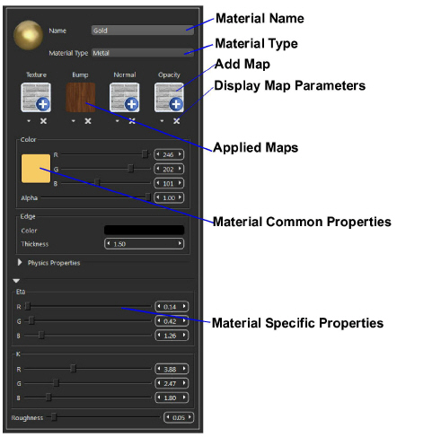
Different types of maps are also applied to the material of the selected geometry in this tab. These maps have different effects on the look of the 3D model, thus reducing the needed modeling time and complexity. Each map has its own parameters that are accessed by clicking the down arrow under the map’s image file. Add a map to a material by clicking the ‘+’ image, or delete by clicking the ‘x’ button under the material image.
|
Texture Maps |
Can be applied to any material type. Apply a texture file then fine tune the different parameters to get the required effect. |
|
Bump Maps |
Are used to simulate the look of geometric details on objects, so that these details don't have to be modeled in the geometry itself. Bump maps can be set to a texture of any format. Notice that even when a colored image is supported, it is still utilized as if it were in gray scale, since bump maps utilize the intensity and not the color of the pixels. The bump map basically simulates the effect of changing the surface level of the object, where bright pixels in the bump map image simulate heightened areas, and dark pixels represent lowered areas. |
|
|
On top of the regular texture, scale, and offset properties, the bump map has one additional parameter, strength, which can be set to any positive value, and allows the bump effect to be modified so that higher values make the effect stronger and more pronounced, causing object to appear less smooth. |
|
Normal Maps |
Are similar to bump maps and are used to simulate the look of geometric details on a 3d object. The difference is that while a bump map uses, a gray scale image to map the height of the surface, in the normal map a colored (RGB) image is used to map the direction of the normal in addition to its height. A normal map enables finer control, but requires three channels (R,G, and B) to perform normal calculations. Normal maps are usually generated by specialized software, which give an RGB normal map image according to the desired effect. A number of usable normal maps can be found on the Internet. |
|
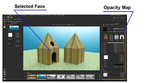
Opacity Maps |
Specify holes, transparent areas, and opaque areas on the mapped object. The image itself contains the opacity data in the following way: |
• Black pixels in the image map represent holes.
• Gray pixels represent semi-transparent areas (as brightness increases, opacity increases).
• White pixels represent opaque areas.
In the image shown below, opacity maps were applied to the bird-house on the left. These maps gave the effect of having a door and window without having to do more modeling.
This part of Kinetics interface, accesses to application settings, registration, help and more.
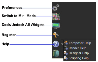
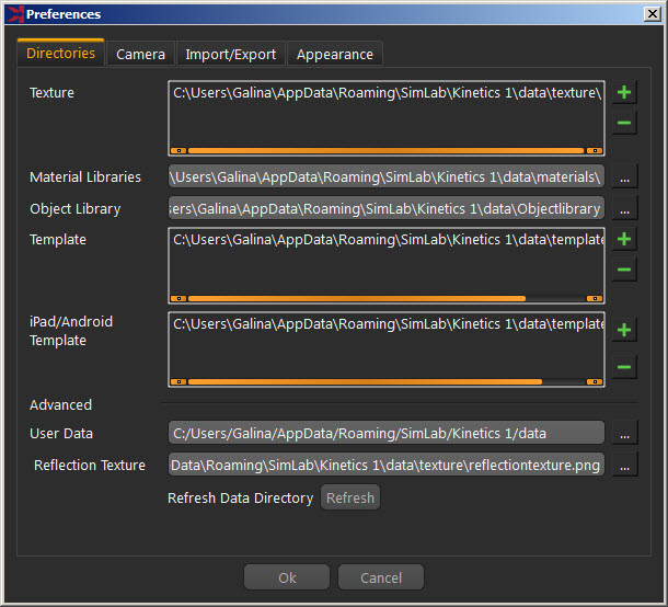
Change the setting in each created scene separately or designate common settings to be used for all new scenes. This is done in the Preferences dialog. This dialog has four tabs, described below:
In this tab change the default directory(s) for Textures, Material libraries, Object Libraries, and Templates used for exporting to 3D PDF, HTML/Web GL, and iPad/Android.
Advanced users can move the User Data directory to a new location. Be sure to copy the original data to the new location before setting the new User Data folder.
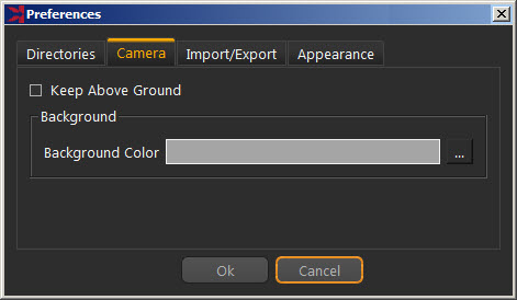
|
Keep Above Ground |
If checked, the camera rotation stops at the ground level, and won’t go below. This option is applicable to Parallel and Perspective cameras. |
|---|---|
|
Background Color |
Is the color of the scene’s background in Kinetics. To display the selected background color, check Preview Background in the Background Settings, under the Render menu, and uncheck the Preview Environment. |
|
Automatically Transform Imported Models |
When checked, the first imported model will be automatically transformed or scaled by the value entered in the ‘First model size to world size’ text box, to the largest dimension of the world size of that scene. The model will be placed in the center of the world. The same transform or scale will be applied to all imported models in that scene. |
|---|---|
|
Tessellation |
This parameter controls the number of triangles to be generated when importing a 3D model that needs tessellation. The following file formats require tessellation: STEP, IGES, and ACIS. |
|
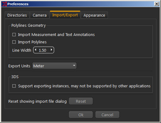
Polylines Geometry |
In this group select to import measurement and text annotations created in the original CAD software. Importing polylines can also be checked, and the width of the imported lines specified. In the image shown to the right, the same model was imported twice, with import measurement and polylines option checked. The first time Line Width was set to 1.5, and then to 5.0 in the second. As can be seen in the image, the tree branches are wider in the second time. |
|
Export Units |
These are units used when exporting 3D models from Kinetics. By default Kinetics uses meters with the option to select different units. All numbers are converted to the selected unit to maintain the correct size of the exported object. |
|
FBX Group |
In this group select the behavior when importing FBX files. The import FBX transform animation option will import the rigid body animation included in the FBX file. An advanced option of the FBX import feature brings in skinning animation to Kinetics. Kinetics does not have the ability to modify this type of animation. It can import it for rendering an animated 3D scene. |
|
Support Exporting Instances in 3DS |
This option detects instances included in the scene when exporting a 3DS file, reducing the size of the generated 3DS file. This function is not supported in all applications reading 3DS files. |
|
Automatically Generate Texture Coordinates |
Texture coordinates for the imported geometry will be automatically generated when this option is checked. |
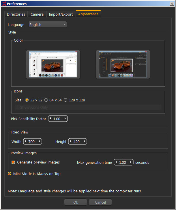
This tab sets the preferred appearance options for Kinetics, including:
|
Language |
Select the language to be used in Kinetics from the supported languages combo box. Changing the language takes effect after restarting Kinetics. |
|---|---|
|
Style Group |
Choose one of two available styles for the Kinetics’s interface. Changing the interface takes effect after restarting the application. |
|
Fixed View group |
If the view mode in the Common toolbar is set to Fixed Size, the values for the Width/Height entered in this group will determine the size of the 3D area. |
|
Preview Images Group |
These are the preview images used in the Basic Tree. If the Generate Preview Images option is unchecked, no images will be generated. A basic 3D Geom image is displayed instead. If checked, Set Max Generation Time, which is the maximum time in seconds spent in generating preview images for the selected geometry, all the way up to its top assembly. These generated images are cashed so if the maximum generation time was not enough to generate all images the first time the geometry was selected, they will be generated the next time. |
|
Mini Mode Is Always on Top |
When checked, this option will display the mini mode of Kinetics on top of any other application. This can be helpful when using Kinetics as a plugin with other 3D CAD applications. |
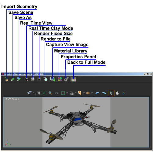
Clicking this option displays Kinetics in mini mode. This mode allows Kinetics to be actively used, while using the 3D design application. The mini mode is equipped with the commonly used functions shown in the image below.
This function docks/undocks all widgets in the Kinetics interface allowing the use of multiple screens so that the Kinetics widgets are set on one screen while the other is used for Kinetics, thus increasing the size of the 3D area.
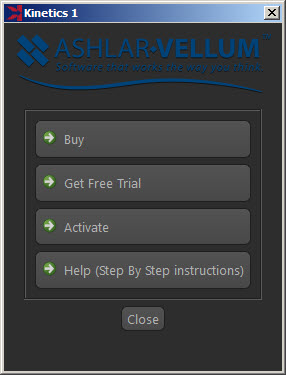
Clicking this option displays the License Dialog that manages the Kinetics license. Buy professional licenses or get free trials here:
http://www.ashlar.com/feedback/index.php?product=Kinetics
Under the Help menu access to different help documents, including;
• This Kinetics User Guide
• Kinetics RT Renderer User Guide
• Kinetics Designer User Guide
• Kinetics Scripting User Guide
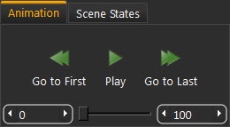
These offer quick access to functions without having to change the workbench. Currently this part includes two tabs, the Animation Tab from the Animation controller, and Scene States Tab from Scene Building controller.
This tab includes a condensed Animation Time Line. Play the animation in the scene from any workbench.
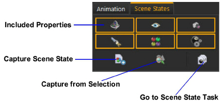
This tab accesses the Capture Scene States function from any workbench. Check the properties to be included in the Scene State. Scene States are also captured for the whole scene, or from a selection in this tab. At any point, click the Go to Scene States Tab, which opens that tab in the Scene Building workbench.
Some functions in Kinetics require actions or selections. This area displays information about the required action.
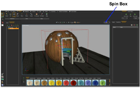
This area displays the last captured Scene State in the Scene States creation. When using any of the drag and drop functions in the Move task, a spin box is displayed in this area. Input values in this box or use its spin arrows.