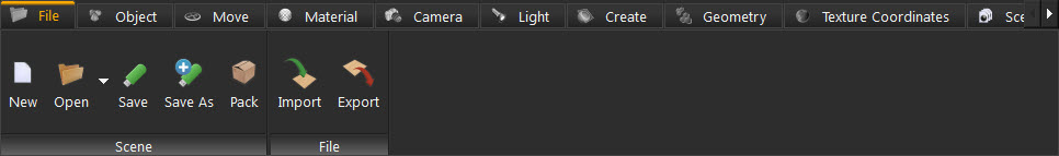
This workbench is equipped with all the tools needed to build 3D scenes in Ashlar-Vellum Kinetics. Upon selecting this workbench the Workbench Task Bar will show the following tasks:
Use this task bar to create new scenes, open existing ones, save, compress, import or export files as needed..
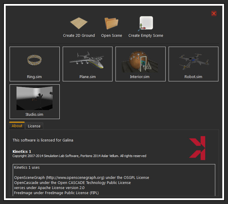
Upon starting Kinetics, or clicking this new button, the New Scene dialog appears. In this dialog create a 2D ground scene, open a scene, or create an empty one. Thumbnails for the last opened scenes are displayed in this dialog for quick access. This recent files list is also accessible from the arrow beside the Open icon.
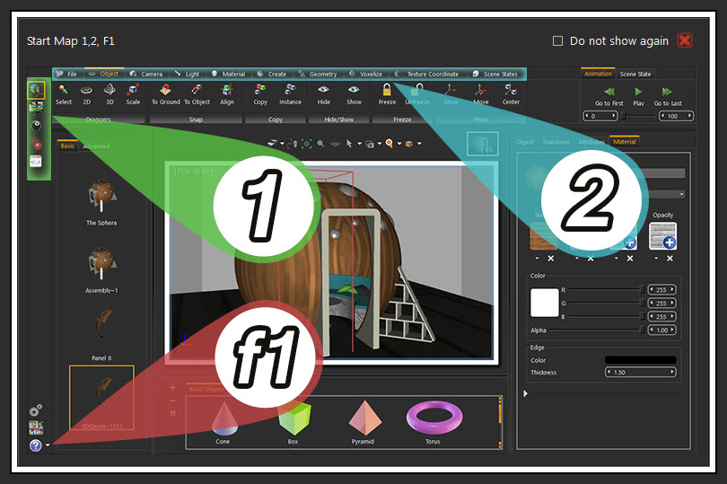
Clicking the Open Scene icon button in this dialog, or the Open icon in the File task bar, displays the Open Kinetics file dialog. In this dialog open already created *.sim files. After selecting the scene type, an informative window appears, describing the new interface. Select the workbench to work with first, and then the task. Check Do not show again to stop this window from appearing.
Both function buttons open the Save Kinetics file dialog to select the name and location for the created *.sim file.
This function button displays the Pack the Scene dialog box, in which *.zip file is created, based on the selected file format.
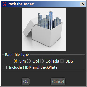
The packed *.zip file includes all 3D models in the scene, along with their materials, and textures. HDR files and BackPlates is optionally included. Packing a scene is necessary to share 3D scenes created in Kinetics with others.
Both function buttons open the corresponding Import/Export Geometry dialog box. The import function builds scenes filled with 3D models form different file formats. The export function, on the other hand, shares the created 3D scene with others in different formats.
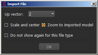
Clicking Import displays the Import Geometry dialog box, to browse to the 3D geometry to import. Upon selecting a 3D file, the Import File dialog appears. In this dialog set different options for 3D import, including:
|
Up Vector |
Z axis is selected by default. The user can choose a different access depending on the design of the imported 3D geometry. |
|---|---|
|
Scale and Center |
This option when checked will scale the imported geometry to fit into the 3D scene. It will also import it to the center of the scene. |
|
Zoom to Imported Model |
When checked, this option zooms the camera to the imported geometry. The Keep Dynamic Link option is described below. Check the Do Not Show Again for this File Type option, to stop this dialog from appearing upon importing this file format. |
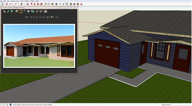
This option in the Kinetics import function improves working with 3D design applications. It keeps the dynamic link/automatic update between the 3D model design application and Kinetics when the Keep Dynamic Link option is checked in the import dialog.
In the images shown below the house designed in Google SketchUp was imported into Kinetics with the dynamic link checked. Different materials and texture were applied to the house model in Kinetics and real time rendering was started.
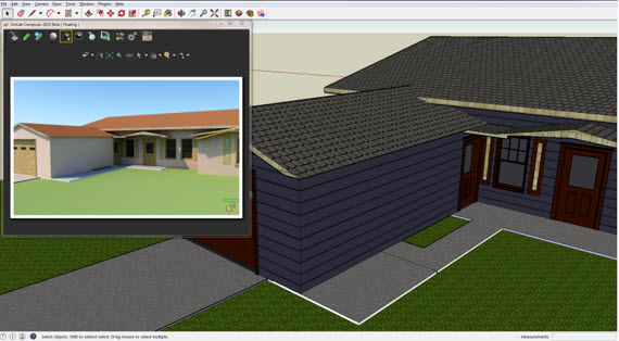
In SketchUp the model has been changed and saved so that the garage area was made bigger. To keep the dynamic link, Kinetics issues a message about the model’s design change.
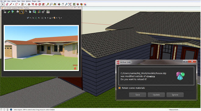
In this dialog save the model in Kinetics with the old design. Then clicking Update with the Retain Scene Materials option checked, updates the design model while keeping Kinetics materials and textures.
Kinetics supports importing the following industry standards CAD/3D file formats:
|
File Format |
Source Package |
Kinetics |
|---|---|---|
|
XAML |
Standard format |
|
|
3DXML |
CATIA |
|
|
SKP |
SketchUp (up to ver 2014) |
|
|
3DM |
Rhino (up to ver 5) |
|
|
SLDPRT, SLDASM |
SolidWorks (up to ver 2014) |
|
|
SAT |
ACIS |
|
|
STEP |
Standard CAD format |
|
|
IGES |
Standard CAD format |
|
|
U3D |
Standard format |
|
|
3D PDF |
Adobe Acrobat (U3D Based) |
|
|
DAE |
Collada (Standard format) |
|
|
FBX |
(up to ver 2014.1) |
|
|
3DS |
3DS |
|
|
OBJ |
Wavefront |
|
|
STL |
Stereolithography |
|
|
DWG |
AutoCAD (Up to 2015) |
|
|
DWF/DWFX |
Autodesk Standard |
|
|
DXF |
AutoCAD |
|
|
OSG |
Open Scene Graph |
|
|
ipt, iam |
Autodesk Inventor (up to 2015) |
|
|
X_T, X_P |
Parasolid |
|
|
IFC |
IFC |
|
|
par, asm, psm |
Solid Edge (up to ST6) |
|
|
Zim |
Kinetics Archive |
|
|
Sim |
Kinetics |
|
Supported Export Formats
3D scenes built using Kinetics can be exported in the following file formats:
|
Export File Formats |
|---|
|
3D PDF (*.pdf) |
|
HTML 5 (*.html) |
|
osg (*.osg) |
|
osgb (*.osgb) |
|
ive (*.ive) |
|
obj (*.obj) |
|
DWF (*.dwf, *.dwfx) |
|
DWG (*.dwg) |
|
DXF (*.dxf) |
|
SketchUp (*.skp) |
|
3DS(*.3ds) |
|
U3D (*.u3d) |
|
KeyShot (*.bip) |
|
Collada (*.dae) |
|
FBX (*.fbx) |
|
DirectX (*.x) |
|
Indigo (*.igs) |
|
STL (*.stl) |
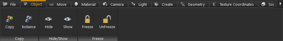
Upon selecting this task, the workbench task bar will show the functions for creating duplicates for 3D objects, as well as hide/show objects, and freezing capabilities.
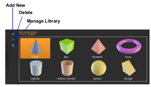
The Library Panel, on the other hand, will change to show the Basic Shapes Object Library. This library provides users with quick access to frequently used 3D models. In this panel add new items to the Basic Shapes group or delete others. Clicking the Manage Library button, creates new groups and manages existing ones.
Kinetics supports the creation of multiple duplicates of an object. This can be done either by creating a copy, or an instance of that object.
|
Create a Copy |
Creates a copy of the selected object together with a copy of all the materials and transforms it uses. Each of the two copies will have its own materials, and transformations. Thus, changes to the materials’ properties of one can be done without affecting the properties of the other. Different transformations can be applied to each without affecting the other. |
|---|---|
|
Make an Instance |
Creates an instance of the selected object with the same materials’ structure and transforms as the original object. By creating an instance, change the materials’ properties and transformations will be applied to both objects. |
These two functions can be used to hide/show selected geometry in the 3D scene.
These two functions can be used to freeze/unfreeze selected geometry in the 3D scene.
In this tab all functions necessary for positioning geometry in a 3D scene can be found.
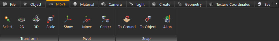
When the user clicks any draggable option in this task bar, a small scroll combination box appears, at the current action area in the top right corner of the 3D area. Use this box to input exact numbers for translation/rotation/scale or just scroll up and down. If you prefer, freely drag the 3D geometry, into the 3D area using one of the tools described in the table below.
|
Button |
Effect |
Short Cut |
|---|---|---|
|
|
Empty the selection |
ESC |
|
|
Move 2D, allows moving the geometry in the X and Y directions, and rotating around the up vector (Z axis) |
1 |
|
|
Move 3D, allows movement in all three directions, and rotation around all three axes |
2 |
|
|
Uniform Scale, used to scale geometry uniformly |
3 |
The pivot of a 3D geometry is the point around which transforms applied to the geometry will be done.
This function shows the pivot for the selected 3D geometry in the 3D area, with drag icons. These icons move and rotate the pivot in any direction.
This function snaps the pivot point to another point location. Make use of the Pick Mode options described in the Common Toolbar, to help in selecting an exact point. After selecting the point, either click the Approve or Decline icon in the upper left corner of the 3D area.
With this function select two points and the pivot of the 3D geometry is snapped to the center between them. Again, make use of the Pick Mode options described in the Common Toolbar to help in selecting exact points.
The snap functions are used for aligning 3D objects.
|
Snap to Ground |
Snaps the selected object(s) to the ground. |
|---|---|
|
Snap To Object |
Displays a message in the messages area, at the top left corner of the 3D area, prompting for the selection of the object to which to snap. |
|
Align |
This function is used with Kinetics Picking Modes, in the Common Toolbar to align selected geometry(s) along selected axes. |
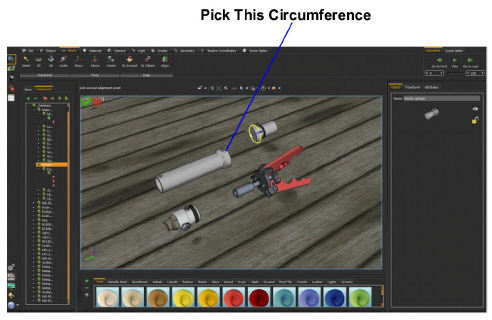
Align Example
In the images shown below, we need to align different parts to the main cylinder of the gripper. Change the View mode to Solid Illustration to benefit from Kinetics picking modes. This generated edges for different parts in the scene. Pick the part(s) to move and then click the Align Objects tool. A message appears in the Message area indicating the need to pick the first alignment point. Choose Pick Center Of Curvature from the Pick Mode in the Common Toolbar, and select the circumference of the inside cylinder.
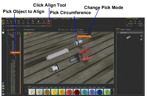
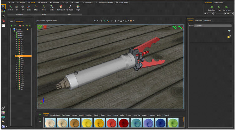
The message will change to pick the second alignment point, so pick the outer circumference of the main cylinder, with the same Pick Mode.
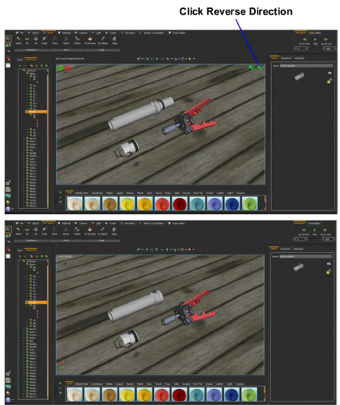
The cylinders will be aligned with two directional options in the upper right corner of the 3D area. Click the reverse direction in this case.
Repeat the same steps with the other sub-assemblies, to align all the parts.
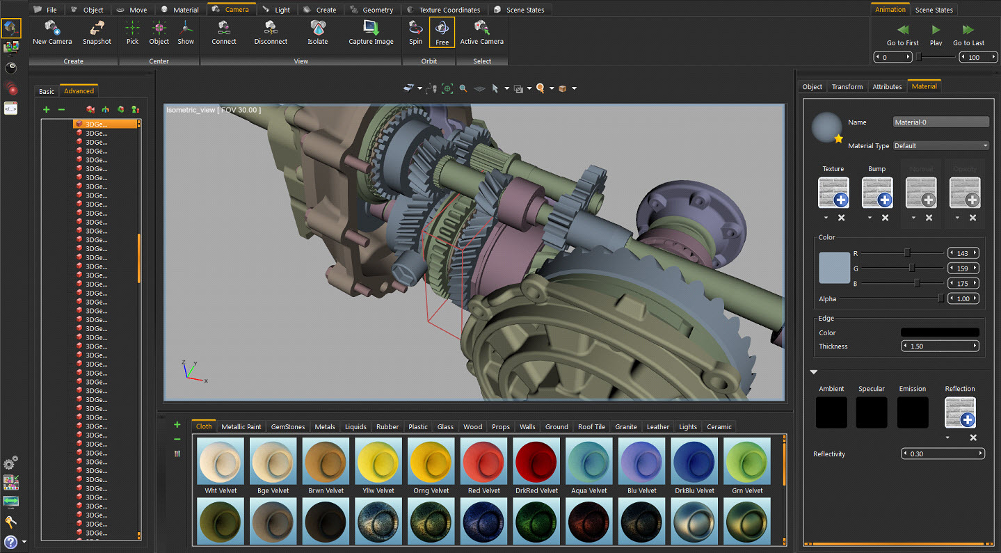
In the Scene Building Workbench it is important to apply materials for different objects in the 3D scene. The Material Task Bar includes all the functions needed for material application, and materials management.
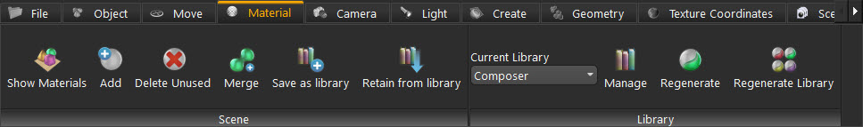
This function button will display the Scene Materials dialog box, which includes the material functions shown in the image below. Some of these functions are included the Material Task Bar, others are found only in this dialog.
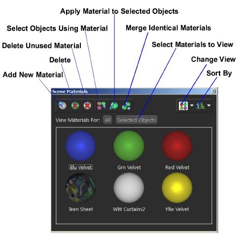
This function deletes the selected material from the Scene Materials dialog. If the material is being used by objects in the scene, a dialog will appear asking for a selection of a replacement material before the deletion.
This function selects all objects in the scene using the selected material in the Scene Materials dialog. These will be highlighted in the Object Tree and in the 3D area.
Apply Material To Selected Objects
To use this function select the object(s) first, then select a material from the Scene Materials dialog or the from the Material Library. After that, click this function and the selected material is applied to the selected objects.
In cases where more than one object in the 3D scene is using the same material, different copies of that material will appear in the Scene Materials Window. This function clears the Materials dialog of unnecessary duplicates.
This display option is available to change the way the materials are displayed in the Scene Materials dialog. Materials are displayed in Large or Small icons, or can be shown as a list.
Sort By Name/Sort By Attributes
Select to sort Scene materials either by name or by attributes as desired.
This function creates a new default material-type and adds it to the Scene Materials dialog. The new material with all of its properties is shown in the Properties Panel.
This function deletes all materials not referenced by any object in the scene. This function is also found in the Scene Materials dialog.
After applying all materials for all geometry in a 3D scene, clicking this function displays the New Material Library window. In this window input a name for the new library, then click OK. This saves the applied scene materials in a library and shows it in the Current Library combination box, and in the Manage Material Libraries panel.
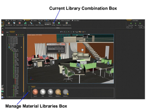
Retain from Library
Before clicking this function button, first select the library to use in the Current Library box. This function will reapply materials included in the selected library to the different geometry based on previously assigned materials names.
This bar includes all of the necessary functions for creating, aligning, and setting the different cameras in a 3D scene. Selecting this task has no effect on the Library Panel making it possible to set the needed library. Created cameras are optionally exported to 3D PDF, and HTML files.
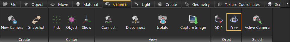
Clicking this function creates a new camera in the 3D scene and adds it to the object-tree. Change the view of the created camera in different ways:
• Using any of the Move tools, in the Move Task Bar.
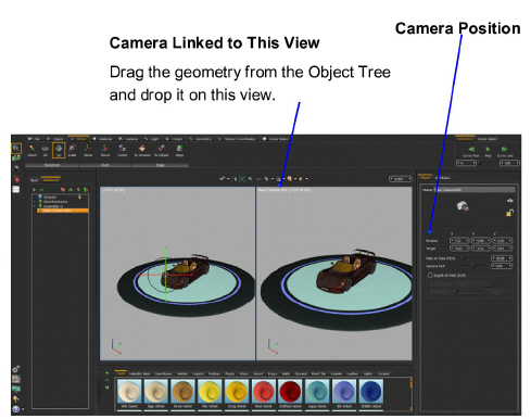
• Linking the camera to a view in the 3D area, either by dragging the camera onto the view or using the Connect function. Then changing the orientation of this view it is saved in the linked camera.
• Selecting a camera in the 3D scene to display its properties in the Properties Panel. Adjusting the Position Parameter in this dialog changes the camera location and its view.
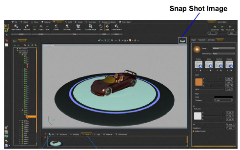
This function creates a scene state of the current camera. This scene state is shown in the Current Action area as well as in the Library Panel of the Scene States Task. Since this scene state is a camera state, it will be added to the All and Camera Tabs, of the Scene States Library.
This function sets the Target Vertex for the active-view camera. It displays a message in the message area, asking for selection of the vertex for the world center. Selecting a point on any geometry in the scene changes the world center to that selected point. Zooming and rotating is then relative to this point.
This function changes the world center to the center of the selected geometry. If the this button is clicked without selecting any geometry, a warning message appears asking for object selection.
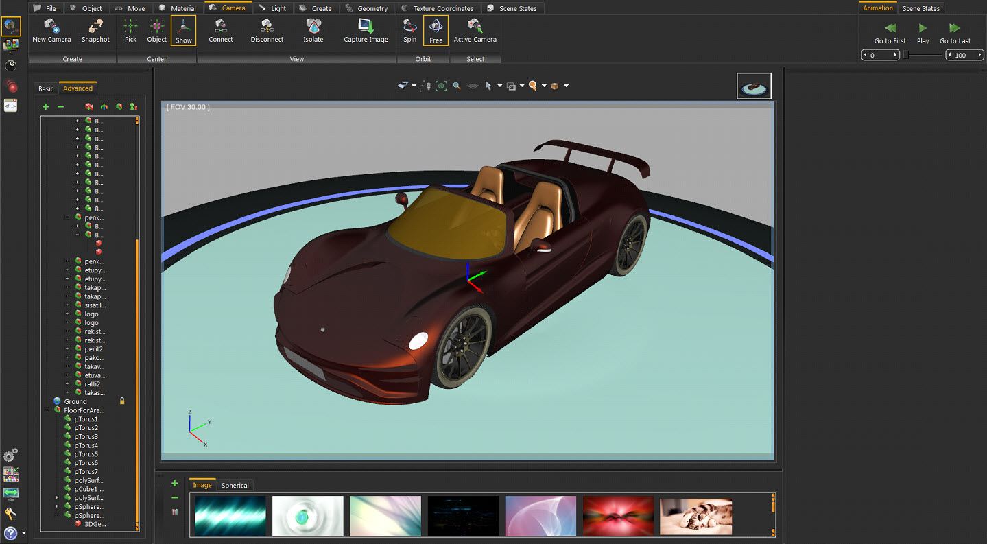
Clicking this button displays a pivot icon with three axis’s representing the camera center, as shown in the image below. This is helpful for predicting the axis of rotation, especially when exporting into a 3D PDF file.
This function is used as another way for connecting cameras to views. The first way is by dragging a camera and dropping it onto a view.
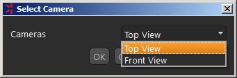
If the scene includes a single camera, clicking this function connects that camera to the active view. If the scene includes more than one camera, the Select Camera dialog appears with a list of the available cameras from which to connect.
The Disconnect function, on the other hand, disconnects any camera linked to the active view. If no cameras are linked to the active view no action is done.
In complex scenes, this tool help to focus on a specific geometry. In the image shown below, a complex crowded engine is under construction. Selecting one of its gears and clicking the Isolate icon hides all other geometry in the scene and focusing on the selected gear.
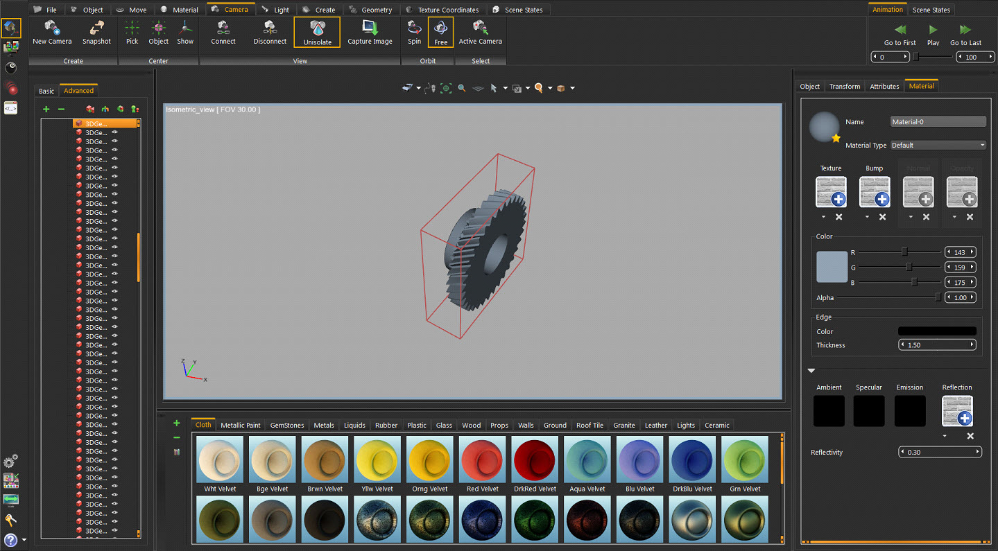
After finishing the work with the isolated geometry, clicking the Unisolate icon shows the rest of the scene.
Clicking this function button opens the Save Image window to save an image of the active view from the opened scene. Browse to the file location, and save the image in (*.png) or (*.jpg) file formats.
By default the navigation mode in Kinetics is free rotation. Selecting Spin changes the navigation mode to spin the world axis.
This function selects the camera linked to the active view and displays its properties in the Properties Panel.
This task bar contains Kinetics’ supported light types in Kinetics which are suitable for interior and exterior scenes. Users can add any of these light sources in addition to the light sources included in the environment image. Light sources in Kinetics, except for the Camera Head Light, are exported to 3D PDF and HTML.
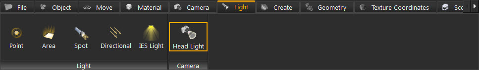
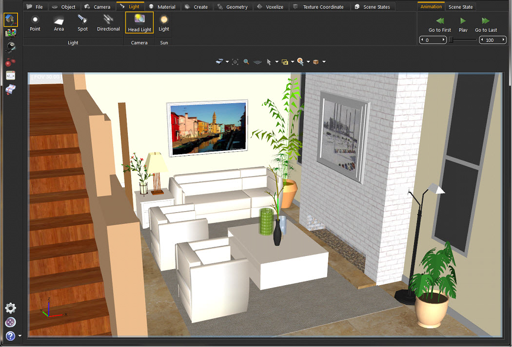
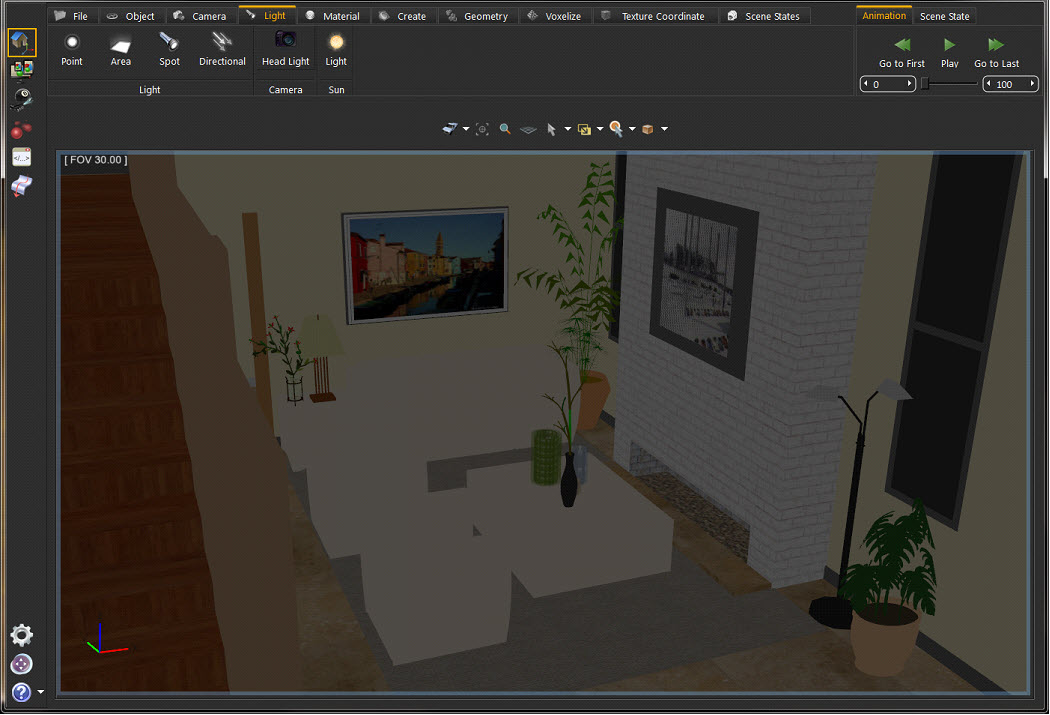
When an *.sim file is created or opened the Camera Head Light will be on to give the user a clear view of the scene. This light will not be exported to 3D PDF or HTML files; it is only for viewing purposes. In the image below the Camera Head light is on, while it is off in the image that allows it.
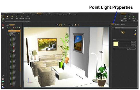
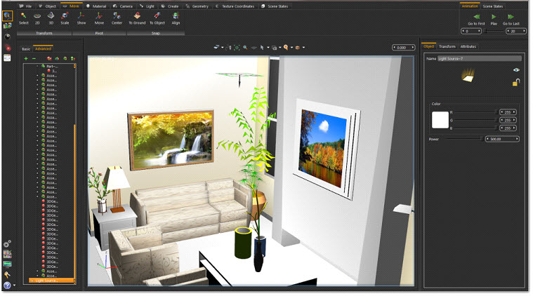
Selecting this light type will create a spherical Light Source and add it to the scene. Point lights can be moved and positioned, using any of the move tools. In the image below, three point lights were added to the scene and were snapped to the side lamps’ geometries using the Snap To Object tool in the Object Task Bar. Fine positioning was also done using the Move 3D tool.
The light properties are found in the Properties Panel, to the right of the 3D area. There a light’s properties are edited, like changing its color, or its power.
Depending on the effect needed, this is another light type to be used. As shown in the image below, the same scene is now lit using an area light.
Like Point lights, area lights have parameters that are changed in the Properties panel.
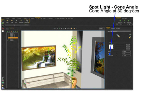
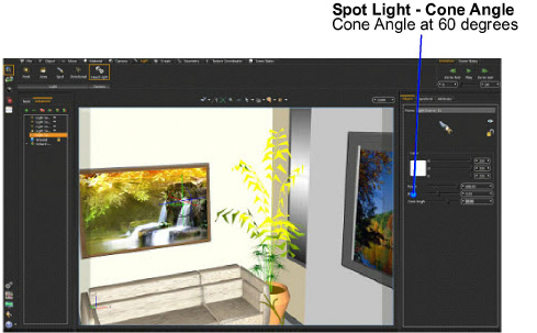
Spot Light is another light type created in Kinetics. In addition to the main light properties, spot lights have a Cone Angle property that sets the angle of the light. In the images bellow the cone angle was set to 30 in the first image and 60 in the second one.
Directional lights are for exterior scenes. The direction of the light is changeable but not its location. Other parameters for this light include light Color, Power, and Name.
Use the task bar to create different Scene elements, adding value to a 3D scene.
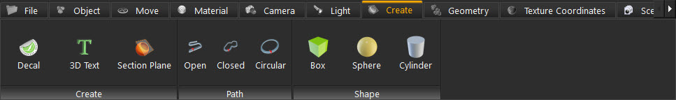
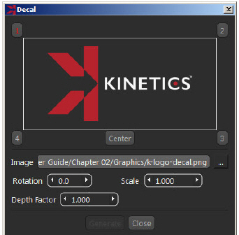
Applying a company Logo or product images to 3D models is made easier with create Decal. Clicking this function opens the Decal window. The parameters in this window are:
|
Requires setting a valid path for a valid image file. |
|
|---|---|
|
Is the rotation angle in degrees to be applied to the decal image. |
|
|
Is a uniform scale value to be applied to the decal image. |
|
|
Is the depth value for applying another image of the decal, in case of applying the decal on more than one geometry. |
After selecting an image, pick four points and a center to set the image location.
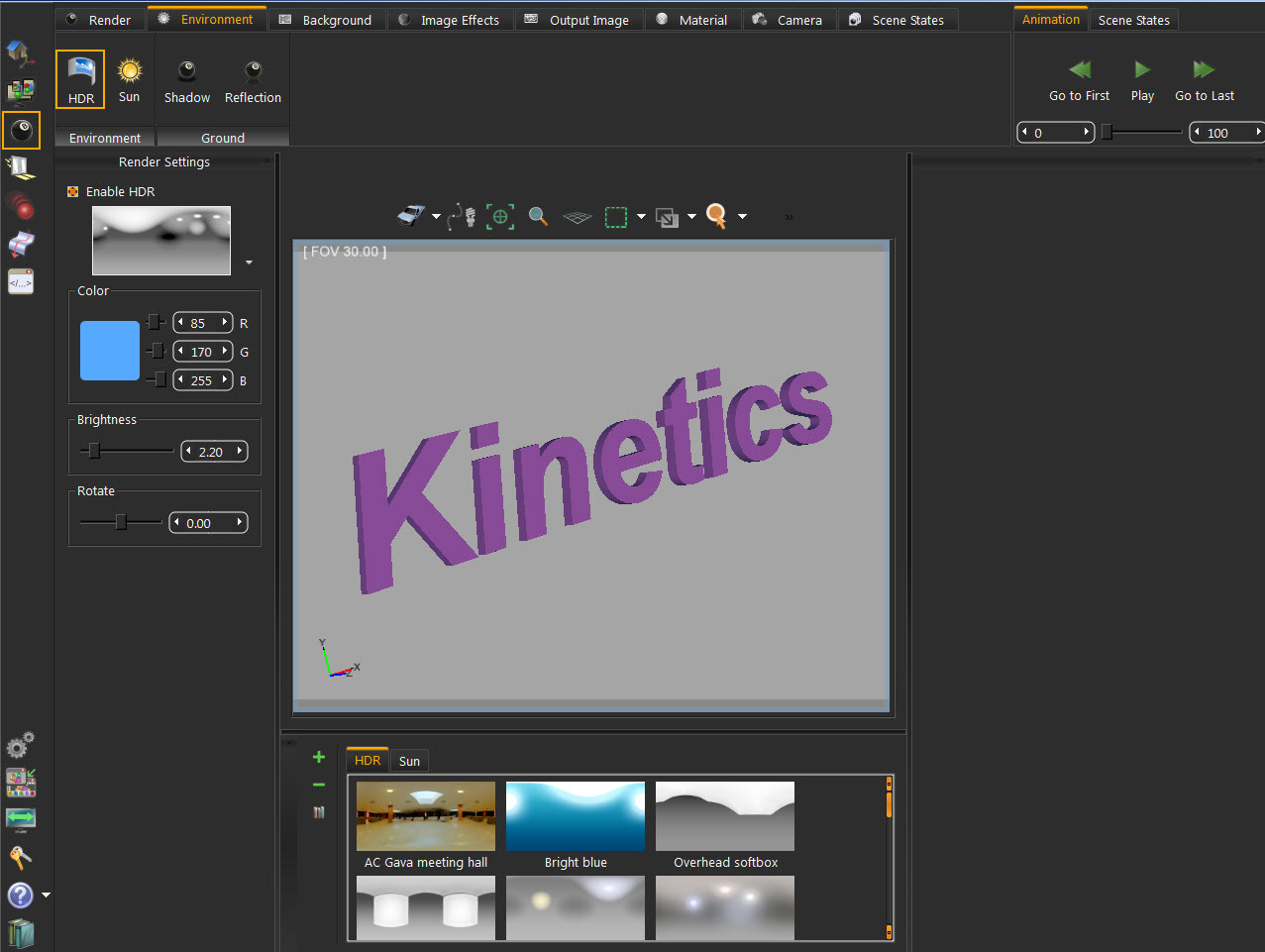
Clicking this function opens the Create Text3D dialog box, where text is typed and formatted. Clicking the OK button creates 3D text parallel to the ground in the 3D scene. An assembly with geometry for all letters in the text is added to the Object Tree. Different transforms are applied to the text. Change the material of the generated 3D Text by dragging material from the materials library and dropping it on its geometry in the Object Tree.
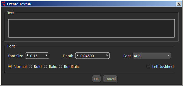
To modify the created 3D text, select the text in the 3D area, or in the Object Tree, to display its properties in the Properties Panel.
Creating a section plane is helpful to show the interior of 3D model. Clicking this function button creates a section plane and adds it to the Object Tree. The newly created section plane is selected in the 3D area with the 3D dragging icon to transform or rotate the section plane.
Section plane effects are exported to the generated 3D PDF files, rendered images, and exported file formats such as OBJ.
By default, a section plane cuts through the whole scene. Using the Break Using Section Plane tool, select the geometry to cut using section plane(s).
In the image shown below, a scene with three spheres inside each other and three section planes were created with different orientations. Select each section plane and use it to cut through the outside and the middle spheres. To do that, go to Geometry task and with the sphere to cut being selected, click the Break By Plane function button. This breaks the geometry into two in the object tree and the 3D area. Repeating this for all three section planes will split each sphere into eight parts. Deleting or hiding some of the parts will result in the shown image.

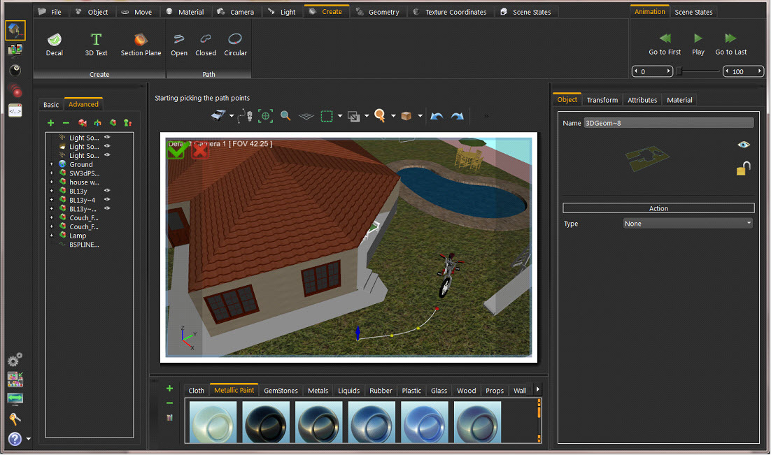
Different paths can be created in the Path group. Create Open, Closed, or Circular paths. To activate a path, select it from the Object Tree. Paths are used to create Path Animation. Upon clicking any path function, a message appears in the Message area asking for the path points to be picked. Approve and decline icons appear at the top left corner of the 3D area to end selecting.
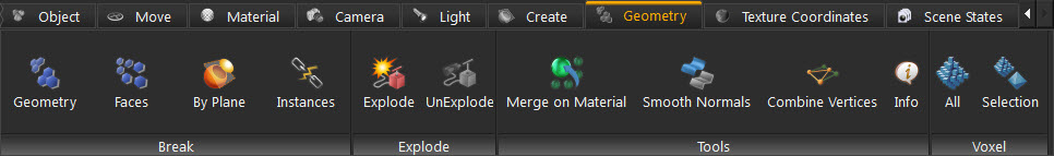
This task bar provides the user with geometry-related tools.
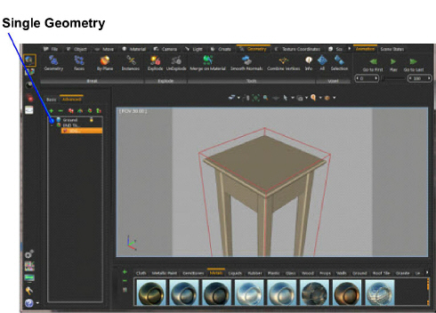
The smallest representation of geometry in Kinetics is 3D Geom. 3D Geom is a geometry that has one transform and one material applied to it. All contents of 3D Geom are moved together, and must have the same material.
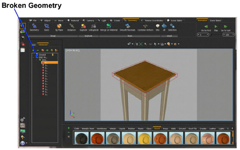
Some model formats do not support saving Object Tree structure. When importing 3D models of those formats, 3D Geom can contain many nonconnected parts. The Break geometry tool breaks a 3D Geom that contains nonconnected parts into multiple 3D Geoms. Each one of the new 3D Geoms is moved separately and assigned a unique material.
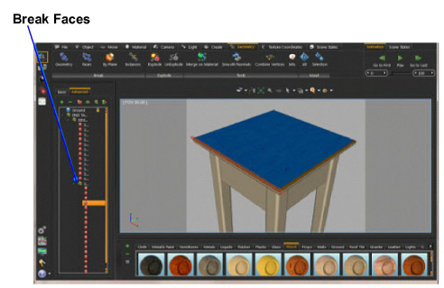
In some cases, when the whole model is connected with no separated parts, it won’t be possible to break the geometry. In such cases, a message will appear indicating that, and suggesting the Break Faces tool.
This tool breaks the selected 3D model into its faces. Each face is converted to a 3D Geom, and added to the Object Tree. Unique materials are assigned to each face. In the above stool example, the top geometry with a different material was broken into its faces as shown in the image below. Different materials were applied to the different generated faces.
This tool selects the geometry to cut through using a section plane already created in the scene, using Create Section Plane from the Create Task Bar. Using the same section plane with different orientations, different cuts can are made on the geometry.
Instances in Kinetics are multiple duplicates of an object using the same materials structure and the same transforms as the original object. Using this function, the instances are be broken so that each one has its own materials and transforms.
Explode function makes it easy to show the components of an assembly. When selected, the explode geometry icon appears, allowing the selected object(s) to be exploded in the X, Y, and Z directions. Rotate the icon to select an arbitrary vector to be used for exploding the assembly.
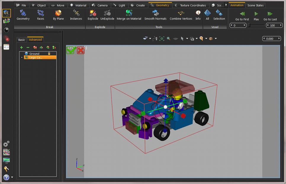
Click either the Approve or the Decline button in the upper left part of the screen when finished with exploding the geometry. Clicking the red Decline button cancels the operation. After completing the explode operation go back to the original model by clicking UnExplode.
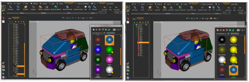
With an assembly selected in a 3D scene, select this tool to merge geometry using the same material into a single unit. In the image shown to the left, the three selected sections of the car model are using the same material. In the right image the Merge function unites them as one
For 3D models with lots of polygons, this tool is used to smooth the normals for rendering and other 3D sharing options.
Vertices having the same texture material and normal direction are replaced by a single vertex, using this tool. This reduces the size and complexity of the 3D model.
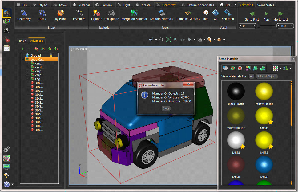
This tool displays the Geometrical Info dialog box, showing the number of Objects, Vertices, and Polygons in the selected geometry. Knowing the number of vertexes and polygons helps estimate the size of the output file, allowing strategic decisions to be made about including or ignoring certain details for sharing efficiency.
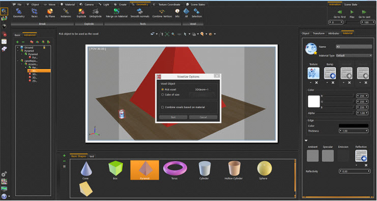
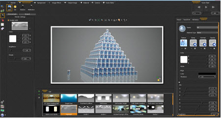
Voxlizing a 3D model rebuilds the model using building blocks (voxels), like LEGOs. Choose the building block to use as well as the whole scene or only selected geometry. Notice that this adds a significant number of polygons to the 3D scene.
The Voxelize Options dialog appears, when clicking any of the voxelization options. The default voxel object is a cube of certain size. Choose a different object by clicking the Pick voxel option. The voxel object must be a geometry in the scene.
The Combine Voxels Based on Material option, if checked, combines all voxels of particular material into one geometry in the Object Tree. If not checked, each voxel has its own geometry in the Object Tree.
Texturing is the process of applying an image to a 3D object, to give it a more realistic look. The Texture Coordinate Task bar gives different options to define the way the image is applied to an object.
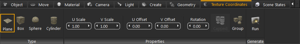
Kinetics is used to generate and update texture coordinates on 3D objects. Kinetics supports four types for generating texture coordinates.
|
Treats the selected geometry as a plane when performing the texture coordinates generation. It can be used to generate texture coordinates on a ground, on a picture frame, or on a computer screen. |
|
|---|---|
|
Suitable for geometries better represented by a box. It has the Caped Property option enabled. |
|
|
Treats the geometry as a sphere. |
|
|
Has the Caped option as the Box type. |
The object used to generate the texture coordinates on should have a material in the Scene Materials with a texture map applied in the Properties Panel. With the object selected, click the generation type, change the properties, and then click Run to generate the coordinates.
The properties to manipulate texture coordinates are:
|
Scales factors in the u, and v directions. Scale the texture either by widening it (giving scale values greater than one) or shrinking it (giving scale values less than one). |
|
|---|---|
|
Shifts the texture in either direction by the value entered. |
|
|
Rotates the texture by an angle, in degrees, entered in this field. |
|
|
Available in the box and cylinder types this represents the object onto which the texture coordinates are being generated. |
|
|
Checked when a textured material needs to be applied on more than one geometry as a whole, this property is useful when generating box texture coordinates on a number of faces. |
After selecting the type of texture generation and setting the properties, click Run to generate the texture coordinates.
Scene States enable users to capture different configurations for the selected 3D model(s), or for the whole scene. Check the properties to include in a scene state, from the Default Apply group in the task bar. Kinetics’s Scene States are smart in capturing attributes. They include any combination of the listed attributes and are helpful in creating scene states for models with different attributes, and setups. To show different products with different materials or versions, Kinetics smart scene states are the answer.
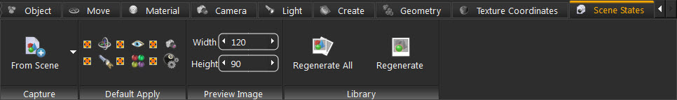
Set the width and height for the scene state Preview Image, to match the settings in the export template.
With the properties checked, click the Capture option for either From Scene or From Selection. The first option captures a scene state for the whole scene with the properties checked in the Default Apply group. The From Selection capture option captures a scene state for the selected model(s), with the checked properties. Depending on the checked properties, the generated scene state is added to the corresponding tab(s) in the Scene States Library.
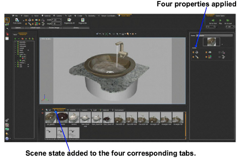
In the image below, different scene states were created for the sink scene. The selected states have the Transform, Visibility, Light Power, and Materials Properties saved. Thus, this scene state is added to the four corresponding tabs in the Library panel, in addition to the All tab.
The Regenerate option builds a rendered preview image for the selected scene state with the size specified in the Preview Image group. The Regenerate All option builds rendered preview images for all the scene states.
Scene states have many useful applications including:
• Renderings
• 3D PDFs
• HTML files
• iPad/Android files
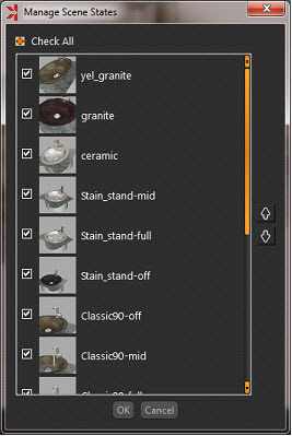
Create multiple scene states for a scene to experiment with views, materials, lights, and prepare different configurations of a scene. With Kinetics Smart Scene States multiple options for creating scene states are available. From the Rendering Workbench click Render Scene States in the Render Task. This opens the Manage Scene States dialog to select the scene states to render and their order. Clicking Ok starts rendering the selected scene states one after the other.
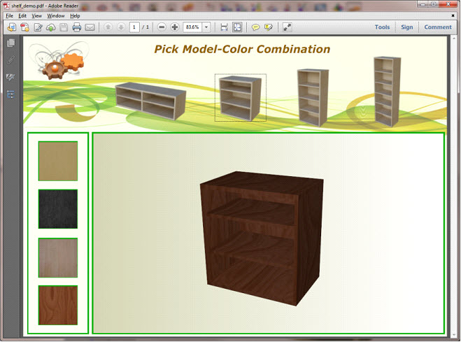
3D PDF Generation with Scene States
From the Sharing workbench go to the PDF tab to create manuals showing products with different materials and configurations. In the image shown below the images of the top shelves were linked to scene states with Camera and Visibility properties included. The material images to the left were linked to scene states that stored Materials property only.
Before attempting to export a 3D PDF file, select the template to use from the PDF Settings dialog. For more details about PDF export, and sharing go to Sharing Workbench section of this manual.
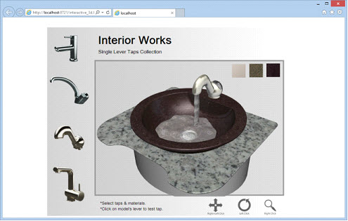
HTML Generation with Scene States
From the Sharing Workbench go to the WebGL tab where smart scene states created inside Kinetics are exported into HTML. 3D sharing on the web is more efficient with smart scene states created for a 3D model. HTML Templates created in Kinetics are linked to scene states creating a more interactive 3D experience.
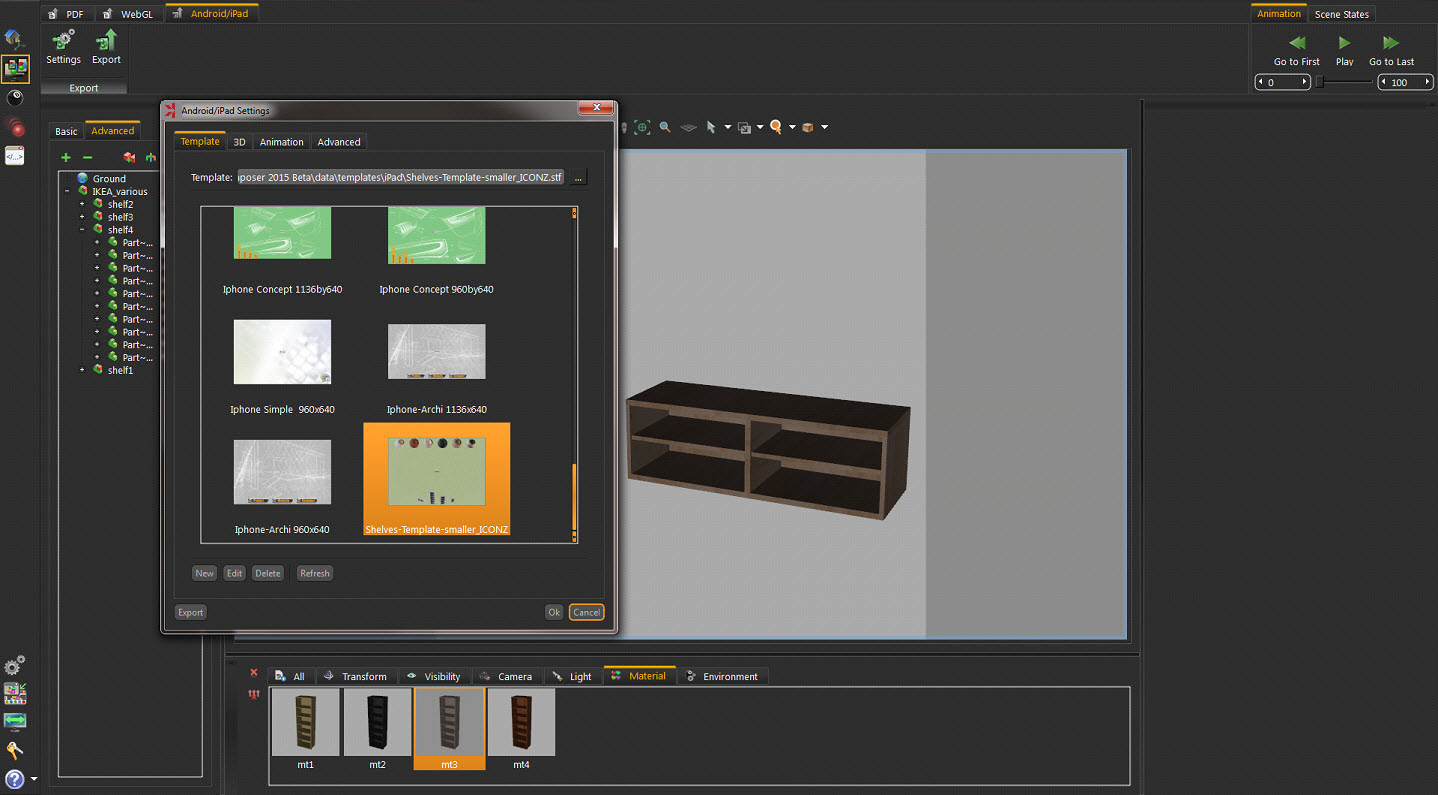
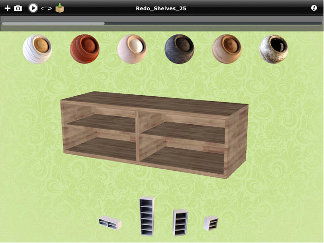
Sharing ideas with customers is evolving with smart scene states exported to Android/iPad. From the Sharing Workbench go to the Android/iPad tab. With a (*.sim) file created with Scene States, and an iPad template created, scenes are exported as *.zim files, viewable by Kinetics CA Viewer.
For more details about Android/iPad export, and sharing go to the Sharing Workbench section of this manual.


 (Windows only)
 (Windows only)


 (Windows only)

 (Windows only)
 (Windows only)
 (Windows only)


