


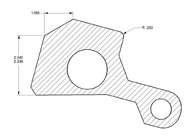
These exercises construct this part using computerized fillets, chamfers, crosshatching and dimensions to perform the following tasks:
• Open Graphite
• Choose from menus
• Create geometry
• Change geometry
• Use the patented Drafting Assistant
• Create construction lines
• Save a document
• Stroke to create construction lines
• Stroke to zoom
• Create chamfers and fillets
• Construct circles
• Trim
• Change the characteristics of lines
• Dimension
• Crosshatch
• Stretch
• Rotate
This exercise starts Graphite.
1. Start Graphite.
If Graphite is already started, please select File>Exit (Windows) or Quit (Macintosh). This makes sure that there are no unintentional settings that will interfere with this tutorial.
• Double-click the Graphite icon in the Graphite folder.
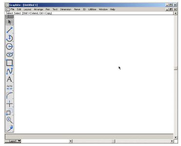
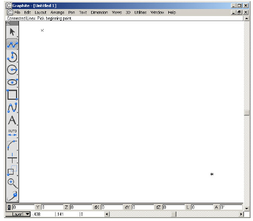
Graphite opens, displaying an untitled document with an empty drawing area.
2. Become familiar with the menus and tool palette.
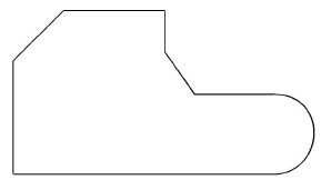
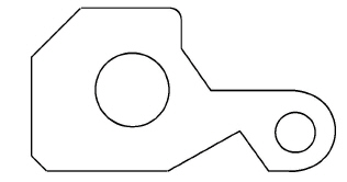
This exercise constructs the basic shape of the part.
1. Select the Connected Lines tool.
• Move the pointer to the Single Line tool icon on the tool palette and press on the small arrowhead in the corner of the Single Line tool.
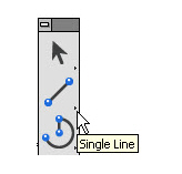
The subpalette appears.

Tech Note: Notice that the icon on the left of the subpalette is part of the tool palette display and the other icons on the subpalette represent the available choices. The icon on the palette changes to reflect the last tool choice, but the icons in the subpalettes are always in the same order, regardless of which tool is on the palette.
• Drag across the subpalette until the Connected Lines tool highlights.
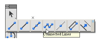
The Message Line indicates that the Connected Lines tool is selected and reads, Connected Lines: Pick beginning point. It remains the active tool until another tool is chosen.
2. Draw the first vertical line 2.25 inches long.
• Position the pointer in the lower left of the drawing area.
• Click to set the first point.
Tech Note: The Drafting Assistant’s construction lines aid in precise placement. The predefined construction lines are vertical, horizontal and at a 45 degree angle to existing geometry points. When the pointer is near such a location the construction line appears and the word on appears next to the pointer.
• Move the pointer up until the Drafting Assistant’s vertical construction line appears.
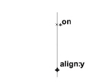
• Move the pointer a couple of inches from the last point (exactness is not necessary), and when on appears on the construction line, click to set the new point on the construction line.
Tech Note: Graphite doesn’t require you to be exact, only close enough to display the feedback. Click the mouse and the Drafting Assistant locks onto the exact location.
• Whatever is typed automatically goes in the Length Status Line field.
At the bottom of the Graphite window, the Status Line displays these data fields. Notice that the Length (L) box is highlighted.

• The numbers on the screen may not match the numbers in this graphic.
• Use either the keypad or the numbers at the top of the main keyboard to type 2.25 and press ENTER or RETURN.
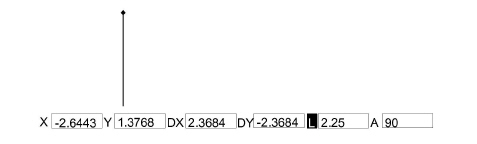
The length (L) goes into the Status Line data field and the line is redrawn to exactly 2.25 inches, beginning at the first position indicated.

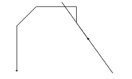
3. Construct the second line 1.25 inches long at a 45° angle from the end of the first line. (Angles are measured from horizontal, not from the previous line.)
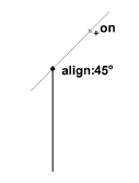
• Move the cursor up and to the right at a 45° angle using the Drafting Assistant construction line as shown above. Click to set a new point an inch or so from the last point.
• Type 1.25 and press ENTER (Windows) or RETURN (Macintosh).
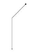
The line segment is constructed at a 45° angle.
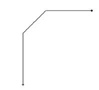
4. Construct a horizontal line 2 inches long.
• Move the pointer to the right to display on for the horizontal construction line.
• Click a few inches from the last point.
• Type 2 and press ENTER or RETURN.
A 2-inch horizontal line is drawn.
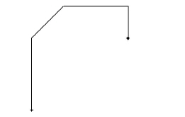
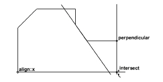
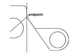
5. Construct a vertical line that ends on the horizontal construction line through the upper endpoint of the first line.
Tip: Whenever the pointer is moved around the screen, the Drafting Assistant examines the existing geometry and displays relevant information about current position.
• Move the pointer straight down until intersect appears, then click to set a point at this intersection.
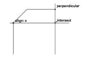
A vertical line is drawn to the Drafting Assistant’s intersection marker.
Tech Note: The current tool remains in effect while commands from the menu are chosen.
6. Use a command from a menu to create a construction line beginning at the endpoint of the last line and at an angle of -55° and then use it to draw a 1-inch line.
• Choose Layout>Construction.
The dialog box appears.
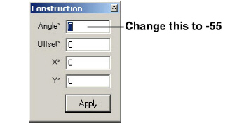
When the pointer is in the dialog box, the angle data field highlights. Enter an Angle for the construction line or an Offset from the point specified by the coordinates. In this step enter an angle for the construction line.
Tech Note: The X,Y coordinates displayed in the Status Line represent the location of the last position selected, which is the location needed for this step. Change the coordinates whenever necessary and everything on the Construction layer is ignored for the Zoom All command.
• Enter -55 (be sure to type the minus sign).
• Click Apply.
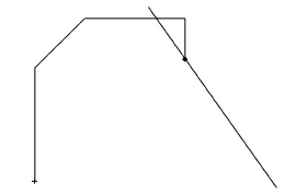
A permanent construction line appears as a dotted line on the screen.
Tech Note: Construction lines created in this way are removed when Layout>Delete Constructions is chosen. Such construction lines are treated like any other line by the Drafting Assistant, except that they are placed on the Construction layer.
• Click the Close box of the Construction dialog button in the upper-right corner (Windows) or upper left corner (Macintosh).
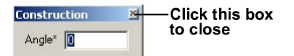
The dialog box closes.
• Instead of the Layout>Construction command you can use the Construction Line tool  from the Line tools palette.
The angle of the construction line is set in the last field of the Status Line.
Note: Classic construction lines are always relative to the zoom level at which they are created. Infinite construction lines pay no attention to zoom level and are infinite in any direction. The construction line is infinite if the Layout>Preferences>Infinite Construction Lines option is checked. If the same option is unchecked, the dotted line appears limited by the endpoints clicked with the mouse while creating it.
• Select the Connected Line tool again in case you used the Constrution Line tool for the last step.
• Click on the construction line, about an inch from the last point.
• Type 1 in the Length field in the Status Line and press ENTER or RETURN.
The line is constructed at a -55° angle.
7. Construct a 1.5-inch horizontal line.
• Move the pointer to the right to display the horizontal construction line through the endpoint of the last line.
• Click.
Tech Note: The Status Line data fields accept mathematical operators to add, subtract, multiply, divide and group values within parentheses. See Appendix A in the User Guide section for a complete list of mathematical operators.
• Type (2+1)/2 in the Length Status Line data field and press ENTER or RETURN.

The 1.5 inch line appears.
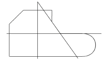
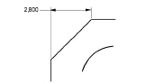
8. Construct an arc from the right endpoint of the last line to a point horizontally aligned with the first point of this exercise.
• If part of the construction is now off-screen, choose Arrange>Zoom All to display the entire part on the screen or double click the middle mouse button.
Tech note: The Message Line indicates how to modify the behavior of Graphite’s drawing tools. For example, after drawing the first segment using the Connected Lines tool, hold down the CTRL (Windows) or OPTION (Macintosh) key to draw an arc instead of a straight line. The pointer changes into the shape of an arc to signify this optional drawing mode.
• Hold down the CTRL (Windows) or the OPTION (Macintosh) key, then move the pointer straight down until intersect appears. The pointer changes to an arc.
• Click the mouse button.
• Release the CTRL (Windows) or OPTION (Macintosh) key.
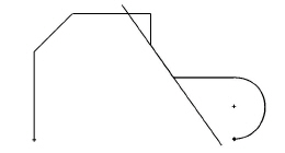
The arc appears.
9. Close the figure.
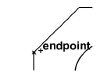
• Move the pointer horizontally to the left to display the endpoint notation for the first line created.
• Double-click to set this point and signal that the connected-line figure is complete.
The outline of the part is now complete.
10. Save the drawing.
A dialog box appears to name the drawing.
• Type part1 and press ENTER or RETURN.
Tech Note: It is important to save often. Power failures and mistakes can destroy hours of work without saving frequently. It is important to save before trying any new multistep operation to be able to revert to the original if the results are not satisfactory.
Accomplishments
• Selecting a tool from the tool palette
• Constructing a part with the Connected Lines tool
• Using the Drafting Assistant
• Choosing from a menu
• Creating a construction line
• Saving a document
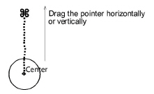
Before proceeding with the drawing, examine the use of Graphite’s stroke commands for creating construction lines, zooming, and displaying points. For stroke commands, hold down the CTRL and SHIFT keys (Windows) or the z key (Macintosh) and drag the z pointer across the screen or click as needed.
Tip: To start a stroke at a precise location, press the z key (Macintosh) or CTRL+SHIFT (Windows) first to wake up the Drafting Assistant if not already in a geometrically precise tool.
|
Drag Diagonally |
|
|
|
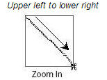
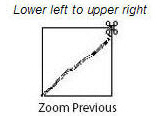
Creates a zoomed-in enlargement centered over the stroked area.
|
|
|
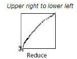
Reverses the zoomed-in stroke to the previous magnification. |
|
|
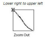
Creates a zoomed-out reduction, so that the current screen reduces to the size of the area defined by the stroke. |
|
|
Reverses the zoomed-out stroke to the previous magnification. |
|
Click |
|
|
On object |
The display of the object’s points is turned on or off. |
Use stroke commands while using any tool. The possible effects that can be obtained with a stroke command depend on the direction the pointer is moved. Even though it is possible to create construction lines and zoom in other ways, the stroke commands come in handy because they can be used while in the process of using other tools from the palette.
Tech Note: It is also possible to use the Construction Line tool from the Line Tools patelle to create construction lines in this exercise.
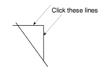
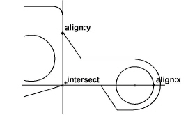
1. Create a horizontal construction line.
• Hold down the CTRL+SHIFT keys (Windows) or the z key (Macintosh).
• Position the pointer at the lower end of the -55° line so that endpoint or intersect appears.
• Drag left horizontally. The pointer trails a dotted line while dragging. Don’t worry if the line isn’t straight.
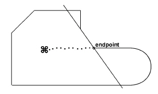
A horizontal construction line appears. Now, there are two construction lines which remain until deletion.
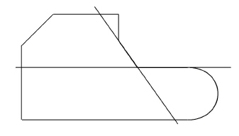
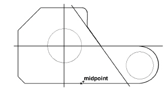
2. Add a vertical construction line.
• Hold down the CTRL+SHIFT keys (Windows) or the z key (Macintosh).
• Position the pointer at the midpoint of the uppermost horizontal line.

• Drag down vertically. A vertical construction line appears. These two construction lines are used later in the tutorial.
Tech Note: These construction lines are placed on the construction layer and can be removed by choosing Layout>Delete Constructions. Since the work layer is transparent, everything on the construction layer is displayed.
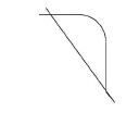
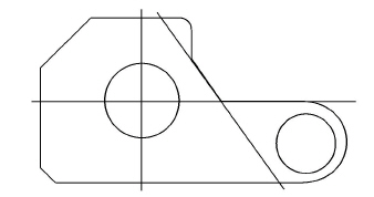
3. Use the stroke command to zoom in on a corner of the drawing to fillet it in the next exercise.
• Hold down the CTRL+SHIFT keys (Windows) or the z key (Macintosh).
• Drag as shown, from above and to the left of the upper-right corner of the drawing across the corner.
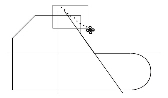
The corner magnifies.

Tech Note: Since all tools work at any magnification, repeat this action for further magnification. But for now, proceed to the next exercise.
Accomplishments
• Creating a construction line by using a stroke command
• Zooming in with a stroke command
Exercise 4: Fillet and Chamfer
In this exercise, fillet one corner of the part and add a chamfer to another.
1. Fillet the corner which was zoomed in on in the last exercise.
Tip: If the geometry is large, hold down the SHIFT key and click inside the corner for single-click filleting. Use this technique when creating the chamfer in Step 3.
• Click the 2-Entity Fillet tool, in the tenth subpalette of the main tool palette. The Message Line reads, 2-Entity Fillet: Pick first entity [Shift = Corner, Ctrl = No trim (Windows) or Option = No trim (Macintosh)].

• Click the horizontal and vertical lines that intersect to form the corner.
The fillet is drawn with a radius of.25 inches, and the corner is automatically trimmed away.
Tech Note: Fillets are automatically constructed with a.25 radius, but it is possible to change the radius in the Status Line, just as the line length was changed earlier. If you don’t want to trim a fillet hold down the CTRL (Windows) or the OPTION (Macintosh) key while clicking the lines that need not to be trimmed away.
2. Return the drawing to its original size.
Tip: It doesn’t matter where you start this stroke or how far you drag to restore the original magnification.
• Hold down the CTRL+SHIFT keys (Windows) or the z key (Macintosh).
• Drag the pointer from the lower right to the upper left of the drawing area.
• Release the CTRL and SHIFT keys (Windows) or the z key (Macintosh).
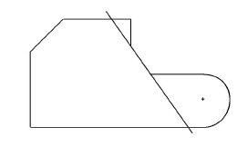
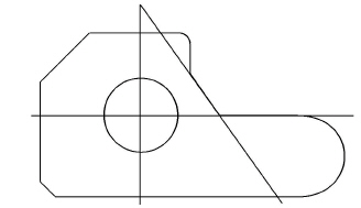
3. Add a chamfer to the lower-left corner of the part.
• Press the Fillet tool to display the subpalette.
• Select the 2-Entity Chamfer tool. The Message Line reads, 2-Entity Chamfer: Pick first entity to chamfer [Shift = Corner, Ctrl = No trim (Windows) or Option = No trim (Macintosh)].

• Hold down the SHIFT key.
• Click inside the lower-left corner of the part.
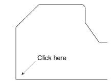
The chamfer is drawn .25 inch from the original corner.
4. Save the work.
• Choose File>Save.
Since the drawing is already named, the part is saved without displaying the dialog box. The length of time it takes to save depends on the complexity of the part being drawing.
Accomplishments
• Constructing a fillet
• Zooming out by using a stroke command
• Constructing a simple chamfer
In this exercise two holes are added to the part, one of which is offset from a specified location.
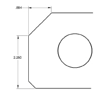
1. Construct a hole, 1.5 inches in diameter, centered at the intersection of the vertical and horizontal construction lines created in Exercise 2.
• Click the Center-Point Circle tool. The Message Line reads, Center-Point Circle: Pick center [Ctrl = Copy previous (Windows) or Option = Copy previous (Macintosh)].

• Click the intersect point of the horizontal and vertical construction lines to indicate the center of the circle.
• Move the pointer an inch or so in any direction and click.
A circle is drawn with the center point at your specified location.
• Enter 1.5 in the D (Diameter) data field of the Status Line.
• Press ENTER or RETURN.
The circle is redrawn with a diameter of 1.5 inches.
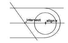
2. Construct a 1-inch hole that is offset.06 inches in the negative x-direction from the center of the arc of the part.
• Move the pointer over the arc until the Drafting Assistant displays the + indicating the center of the arc.
• Move the pointer to the + to display the center feedback.
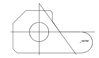
The Center-Point Circle tool is still the current tool.
• Click to position the center of the circle.
• Enter 1 in the D (Diameter) data field but do not press ENTER or RETURN.
• Click in the X data field of the Status Line and place the text cursor at the end of the existing entry.
• Type –.06 after the value in the X data field (don’t forget the minus, since you are creating an equation from the existing X value) and press ENTER or RETURN.
Tech Note: The cursor must be at the end of the existing entry. Otherwise the circle will not be located properly.
The circle is drawn with a diameter of 1 inch and its center is offset by –.06 inches.
Tip: The center can be drawn just by clicking the center and entering a value for the diameter.
3. Save the work.
Accomplishments
• Constructing circles
• Using point offsets
In this exercise the part being constructed is modified. First, add a cut-out section to the bottom edge, and then change the diameter of one of the holes.
1. Add the cutout, beginning at the midpoint of the bottom edge and extending to the –55° construction line.
• Select the Connected Lines tool.
• Click at the midpoint of the bottom line of the part.
• Move the pointer to the arc to display the center point of the arc.
• Move the pointer along the –55° line until the intersect point of the center point and the –55° line appears.
• Click.
• Move the pointer to the intersect point of the –55° construction line and the bottom line of the drawing.
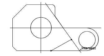
• Double-click.
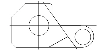
The lines are drawn and remain selected. They must be selected to perform the next step.
• Select the Simple Trim tool from the Trim Tools palette of from the context menu.

The Message Line reads, Simple Trim: Pick section to trim [Shift = Select boundary, Ctrl = Relimit (Windows) or Option = Relimit (Macintosh)].
• Position the Trim pointer dot over the line segment to be discarded.
Tech Note: In order to use the Simple Trim tool, first select the lines that define the boundaries of the geometry to trim away, not the line to trim. In this case the lines are already selected.
•
• Click.
The line segment trims.
2. Delete the construction lines since they are no longer needed.
• Choose Layout>Delete Constructions.
The visible horizontal, vertical and –55° construction lines created in this tutorial are removed. The Drafting Assistant’s dynamic, on-the-fly construction lines continue to display when the pointer of an appropriate tool is moved near geometry.
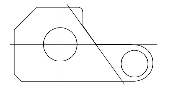
3. Change the diameter of the hole on the right to .75 inch.
Tip: Press ESC twice at any time to change to the Selection tool.
• Click the Selection tool. The Message Line reads, Select: Select [Shift = Extend, Ctrl = Copy (Windows) or Option = Copy (Macintosh)].

• Click the smaller circle.
• Choose Edit>Edit Objects or right click and choose the Edit Objects option from the context menu.
• Click the word diameter in the Edit Objects dialog box.
• Type .75 and press ENTER or RETURN.
Tech Note: If only one change is made, press ENTER or RETURN; otherwise, make all the changes, then click the Apply button.
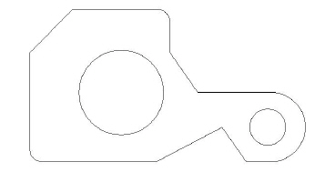
The original circle is redrawn with a .75-inch diameter.
• Click the Close button on the Edit Objects dialog box.
4. Change the Weight and Color of the lines.
• Double-click the Selection tool.
Everything in the drawing is selected.
• Choose Pen>Weight or right click and choose the weight option from the context menu.
Tip: The arrow beside the Weight command in the menu indicates a submenu.
• Choose 0.016 for the pen weight.
All lines are changed to a medium pen weight.
• Choose Pen>Color>Green or right click and choose the Color option from the context menu and Green from the Color drop down menu.
Tech Note: The selected lines don’t change to green until they are deselected.
• Click in the drawing area where there is no geometry, deselecting the lines to see the new color.
The lines in the drawing are displayed in green.
5. Save the work.
Accomplishments
• Trimming
• Deleting construction geometry
• Editing geometry with the Edit Objects command
• Selecting all objects
• Changing the pen weight
• Changing the pen color
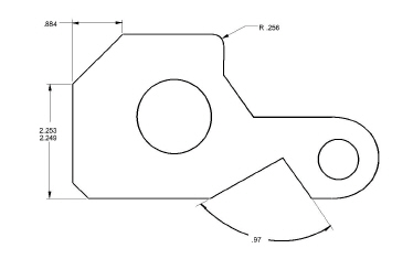
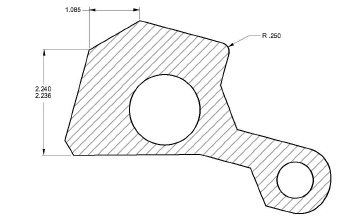
In this exercise dimensions are added to the drawing.
Tech Note: Dimensions automatically go on the Dimension layer rather than on the work layer. This is a unique feature of dimensions and the Dimension layer. If the Dimension layer is removed, create a new one to complete this exercise. If the Dimension layer is hidden, then the dimensions will be placed on the current work layer.
1. Dimension the horizontal length of the 45° line.
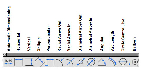
• Choose .Dimension palette from the main tool palette.
Tip: Since the layers are transparent, the geometry and dimensions are displayed on both layers at the same time.
• Select the Horizontal Dimension tool. The Message Line reads, Horizontal: Pick first dimension point.

• Select the left end of the line to be dimensioned by clicking the lower endpoint of the 45° line.
The hot spot on the pointer moves to the right.
Tech Note: Take a moment to examine the pointer that appears. The dot on one leg of the pointer marks the hot spot for the performed action.

The location of the dot indicates which side of the object to select. The dot changes positions as the dimensioning tool is used. This type of pointer is a smart pointer because it gives important information in a multistep process. Many of Graphite’s tools use the smart pointer.
• Click the upper endpoint of the 45° line.
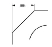
The dimension appears, but the text is in a location that may be changed.
• Move the pointer to the dimension text to display the 4-way Move symbol.

• Drag the text to the left horizontally until it is about .5 inch from the left leg of the dimension.
The dimension text is repositioned.
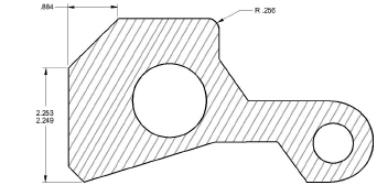
2. Dimension the vertical line on the left.
• Select the Vertical Dimension tool. The Message Line reads, Vertical: Pick first dimension point.

• Click the lowest point of the chamfered corner.

• Click the upper endpoint of the vertical line.
Tech Note: The order of the selection determines the placement of the dimension text. Selecting in the order shown on the smart pointer, the text appears above horizontally dimensioned geometry or to the right of vertically dimensioned geometry. Selecting in the opposite order, the text appears below or to the left of the selected geometry.
The dimension appears. Add tolerances at this point.
• Choose Dimension>Linear and select yyy/xxx (limits).

A new group of Status Line data fields appears at the bottom of the screen.
• Click Upper in the Status Line.
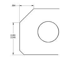
By clicking on the name, the data field automatically highlights, ready for new data to be entered.
• Type .003 and press ENTER or RETURN.
The dimension now reflects a .003 upper tolerance and –.001 lower tolerance.
3. Dimension the angle of the cutout.
• Select the Angular Dimension tool. The Message Line reads, Angular: Select Line.

• Click the arms of the cutout, near the lower (outer) ends of the lines.
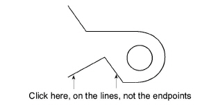
Tech Note: The placement of the angular dimension is controlled by which side of the mid-point is selected on each of the lines. There are four possible combinations.
The angle is measured from the endpoint nearest to the clicked location.

4. Add a radial dimension to the fillet.
• Select the Radial Arrow Out Dimension tool. The Message Line reads, Radial Arrow Out: Select arc/circle.

• Choose Dimension>Linear and select xxx from the submenu to return to dimensions without tolerance.
• Click outside (but near) the filleted corner. Make sure the on notation appears on the arc.
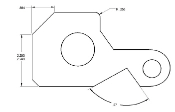

The radial dimension appears on the side of the arc where you clicked.
Tip: Radial dimensions are created with a single click of the mouse. The text appears on the side of the arc that is clicked.
• Choose Dimension>Hide Palette.
The Dimension tool palette disappears.
5. Remove the angular dimension.
• Click the Selection tool.
• Click the text portion of the angular dimension.
• Press the DELETE key. The angular dimension deletes.
6. Save this part with a different name (part1a), to be able to use it later for an advanced exercise.
• Choose File>Save As.
The Save File dialog box appears with part1.vc6 listed in the Filename box.
• Click after the 1 of part1 in the data field.
• Type a and press ENTER or RETURN. The part saves with the new name, part1a.
Accomplishments
• Adding dimensions
• Moving dimension text
• Adding tolerances
• Saving a version of a part with a different name
Crosshatching can be added with the part fully drawn and dimensioned.
1. Select the boundaries that define the area to be crosshatched.
• Double-click the Selection tool.
All geometry is selected.
Tech Note: Graphite automatically excludes dimensions from the crosshatching process.
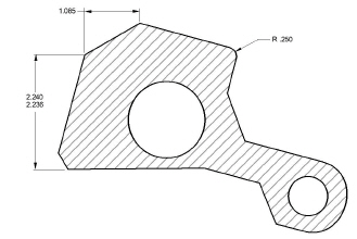
2. Crosshatch the part, indicating Steel.
Choose Pen>Crosshatch.
• Click on the radio button for ISO crosshatching.
• Select Steel from the list of patterns. The display box shows the crosshatching exactly as it appears in the part.
• Click Apply.
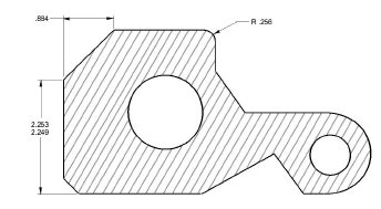
The part is crosshatched.
Tip: Choose Pen>Hatch to apply the current crosshatch pattern to the selected area.
• Close the dialog box.
• Click anywhere in the drawing area to deselect the part.
3. Save the part once again as part1.
• Choose File>Save As. The filename listed is part1.vc6.
• Click after the a in the data field.
• Press the BACKSPACE (Windows) or DELETE (Macintosh) key once to remove the a and press ENTER or RETURN.
Since two documents can not be saved with the same name in the same directory, the dialogue box asks if you want to overwrite the existing file named part1.vc6.
• Click OK. The original version of part1.vc6 is replaced with this crosshatched version.
Accomplishments
• Crosshatching a part
• Saving and replacing an existing version
• Renaming a file
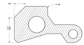
In this exercise you will change the basic outline of the part and see how the crosshatching automatically redraws to accommodate the change.
1. Drag a selection fence around the point where the left point of the cutout joins the horizontal line.
• Click the Selection tool.
• If any part of the drawing is selected, click anywhere in the drawing area to deselect the part.
• Position the pointer above and to the left of the point.
• Drag to a location below and to the right of the point.
Tech Note: To drag, press and hold down the mouse button, drag the mouse to the desired location and release the button.
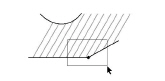
The point is selected, as shown below. If the square selection point isn’t visible, choose Edit>Selectable Points and select again.

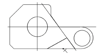
2. Stretch the part so that the left side of the cutout is horizontal.
Tech Note: You can also use the Stretch tool found in the Transformation Tools palette or in the context menu. Before using the Stretch tool, the entire object must be selected. Follow the instructions of the Message line to stretch the object correctly.
• Move the pointer to the selected point until the pointer displays the 4-way Move symbol. 
• Drag the point upward to the top of the –55° line, so that the vertical construction line appears. Do not release the mouse button.
Tech Note: Moving the pointer over this endpoint activates it so that the Drafting Assistant’s construction line passes through it.
• With the mouse button still pressed, drag downward to the intersect point of the Drafting Assistant's construction lines as shown below.
The part is redrawn and the crosshatching is updated, once the mouse button is released.
3. Save the work.
Accomplishments
• Selecting a point
• Using a selection fence
• Activating a point
• Stretching a part
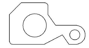
Now that the part is complete, rotate it so that the left line of the newly created cutout is horizontal.
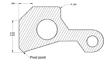
1. Specify the rotation.
• If the part is not selected, double-click the Selection tool.
• In the Transformation subpalette or from the right click context menu, select the Rotate tool.
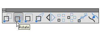
The Message Line reads, Rotate: Pick center of rotation [Shift = Select, Ctrl = Copy (Windows) or Option = Copy (Macintosh)].
• Specify the pivot point (the center of rotation) by clicking the lower endpoint of the left side of the cutout.
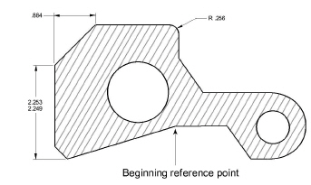
• Specify the beginning reference point (the point that is to move) by clicking at the control point moved in the last exercise.
• Specify the ending reference point by clicking on the horizontal construction line across the bottom of the part.
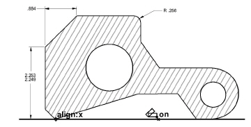
The part rotates.
Tech Note: Notice that the dimensions changed to reflect the new orientation; this is an example of associativity. Graphite maintains an extensive database describing all geometry so that dimensions and locations can be updated quickly.
2. Reduce the visual display of the part.
• Select the Zoom Out tool to display the entire part on the

screen.
Tech Note: Zooming does not change the actual measurements of the part.
The Message Line reads, Zoom Out: Pick area to zoom [Ctrl = Zoom In (Windows) or Option = Zoom In (Macintosh)]. The Scale data field in the Status Line displays the current scale.
Tech Note: To zoom out, click in the location you want to magnify and scroll forward the mouse scroll wheel or double click the scroll wheel to zoom all.
• Click a location near the larger hole.
The magnification of the part decreases and the location you clicked is in the center of the screen.
3. Save the work.
Accomplishments
• Rotating a part
• Observing associative dimensions
• Zooming out to a specific location
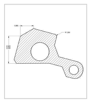
Exercise 11: Printing the Drawing
For the drawing to be useful, transfer it to paper. If the drawing extends past the boundaries of the paper being used, scale it before printing.
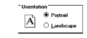
1. Specify the page orientation and paper size.
• If necessary, specify Portrait orientation.
• For plotter, specify the appropriate paper size.
• Click OK.
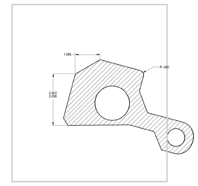
2. Specify the exact area to be printed.
• Click Always Display Page Bounds to display the gray box representing the maximum plotable area of the page.
Tech Note: The page outline appears in the drawing area at all times if the Always Display Page Bounds option is on. When this option is off, the page outline appears only when the Drawing Size dialog box is open or when File>Preview Layout is selected.
Tech Note: The drawing may not look like the right graphic because a different printer, plotter, or paper size may have been specified.
• Click Keep Text Size.
• Click Keep Dimension Text Size.
• Click Fit.
This roughly centers the drawing on the page and scales it to fit.
• Since the scale will be a non-standard value, select the nearest standard size.
• Use the pan hand to position the page around the object.
• Click Apply.
The drawing border is scaled and redrawn so that the part fits on the paper size with the orientation specified in Print Setup.
• Click OK to close the dialog box.
3. Print the drawing.
The drawing is sent to the printer or plotter.
4. Close the document.
The dialogue box asks if you want to save.
• Click OK.
The document closes.
Accomplishments
• Displaying the paper size in the drawing area
• Scaling the drawing
• Printing the drawing