


Additional Features
In this section some of the more advanced Graphite features are introduced. While many features are demonstrated, look through the User Guide chapters for other features which might be useful. In some cases, the exercises do not create a useful part but only show how to use a feature, such as how to trim two lines to make a corner or how to construct a line tangent to a circle. In other cases real parts are created, such as the front and side view of a flange.
The features covered in this section include:
• Corner Trim
• Trim
• Relimit
• Text
• Tangent Lines
• Perpendicular Lines
• Origin (0,0)
• Circle Fillets
• Polar Duplicate
• Polygon
• Parallel Lines
• Mirror Transformation
• Bolt Circle
• Parametrics
• Splines
• Smart Walls
Exercise 1: Trimming and Relimiting
In this exercise investigate some advanced construction techniques. Graphite creates corners and trims or relimits lines. When trimming a line it shortens to its intersection with the selected boundary. Relimiting extends or shortens a line to the limiting boundary.
1. Open a new Graphite document.
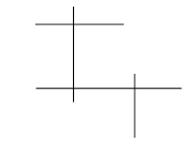
2. Explore the Simple Trim tool.
• Create an approximation of the lines here.
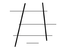
Tip: The exact figure is not important. Learning about how the Trim and Relimit tools function is the objective.
• Hold down the SHIFT key and select the two lines that appear bold in the graphic.
• Select the Simple Trim tool from the Trim Tools palette or from the right click context menu. The Message Line reads, Simple Trim: Pick section to trim [Shift = Select boundary, Ctrl = Relimit (Windows) or Option = Relimit (Macintosh)].

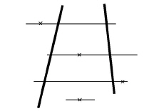
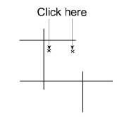
• Click the locations indicated here.
Tech Note: When trimming an entire entity, a prompt appears asking if you want to delete the entire item. Graphite is making sure you want to remove that piece of geometry before it performs the trim.
The lines are trimmed.
Tech Note: For Trim, select what to throw away. For Relimit, select what to keep and it will be trimmed or extended to hit the highlighted boundary.
• Select Edit>Undo or click CTRL+Z four times so that the lines are restored.
• Select the Relimit tool from the Trim Tools palette or from the right click context menu. The Message Line reads, Relimit: Pick section to retain [Shift = boundary, Ctrl = Trim (Windows) or Option = Trim (Macintosh)].

• Click the same locations with the Relimit tool.

The lines are extended to the boundaries.
4. Explore the Corner Trim tool.
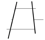
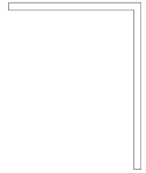
• Create an approximation of the lines below.
Tech Note: Use Undo and Redo to go back to a previous version to correct mistakes.
• Select the Corner Trim tool from the Trim subpalette.
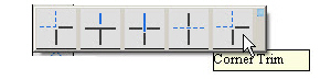
The Message Line reads, Corner Trim: Pick first entity to trim [Shift = Corner, Ctrl = No Trim (Windows) or Option = No Trim (Macintosh)].
• Hold down the SHIFT key and click inside the top corners as shown in the following graphic.
Tip: Either click each line individually or use SHIFT-Click, and click inside the corners.
The lines are trimmed to create corners.
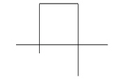
• Select the Simple Trim tool from the Trim Tools palette or from the right click context menu.

• Double-click the Selection tool to select all lines.
• Click the parts of the lines to be trimmed away (those that extend past the corners) to create the figure below.

5. Delete all geometry.
• Choose Edit>Select All or doudle click the scroll wheel to zoom all.
• Press the BACKSPACE (Windows) or DELETE (Macintosh) key.
Accomplishments
• Using the Corner Trim tool
• Observing the difference between trim and relimit
• Deleting geometry
This exercise explores using text.
1. Create a text block.

• Drag a box in the center of the screen. The size isn’t important.
• Click the Width Status Line data field.
• Type 3 and press ENTER (Windows) or RETURN (Macintosh).

2. Change the text characteristics to 10-point Arial.
• Choose Text>Font>Arial.
• Choose Text>Size>10.
Tip: Instead of 10-point Arial use any font listed in Text>Font.
3. Type this text: Submitted by: Ashlar-Vellum.
• Press ENTER (Windows) or RETURN (Macintosh).

Tip: After leaving the Text tool, change the size of the text-entry box by dragging a selection fence around the control points on the right or left side of the box and dragging the points.Draw a box around the text.
Tech Note: Control points are the points defined when the text block is first created and represent the endpoints of the text box.

The text entry box disappears.
Tech Note: The text box appears only when the text is selected. The box being drawn now will always be visible.
• Drag a box around the text so that the text is centered within the box.
4. Group the box and the text so that they can be treated as a single unit.
Tech Note: When several entities need to act as one, group them. In that way one won’t be accidentally selected when the components of the group are meant to be selected.
• Double-click the Selection tool.
• Choose Arrange>Group or right click and choose the Group option from the context menu.
• Drag the box around to see that the text and the box act as a single entity.
5. Type a list of notes.
• Create another text box 2.5 inches wide.
• Change the text characteristics to accommodate a plotter:
|
Font: |
Plotter |
|
Size: |
.156 |
|
Style: |
Normal |
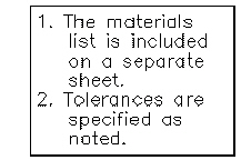
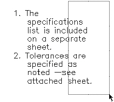
• Type the following without pressing ENTER (Windows) or RETURN (Macintosh).
1. The materials list is included on a separate sheet.
• Press ENTER (Windows) or RETURN (Macintosh) to begin a new line.
• Type the following:
2. Tolerances are specified as noted.
Use the BACKSPACE (Windows) or the DELETE (Macintosh) key to make corrections. Also, notice the word wrap. The text automatically wraps to the next line when a word extends past the right margin.
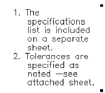
6. Change the indentation so that the text aligns under itself rather than under the number.
• Use the Selection tool to select the note text.
• Choose Text>Indentation. The Indentation dialog box appears.
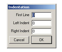
• Click the Left Indent data field to highlight it.
• Type .35.
• Click OK.
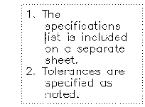
The text shows a hanging indent.
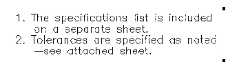
7. Make changes to the text.
• With the text still selected, click the Text tool.
• Double-click the word, materials.
The word, materials and the space after it are highlighted.
• Type specifications and press the SPACEBAR once.
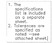
• Click after the period that ends the second sentence.
• Press the BACKSPACE (Windows) or the DELETE (Macintosh) key.
The period deletes.
• Press the SPACEBAR once and type the following:
—see attached sheet.
8. Change the size of the text box.
• Click the Selection tool.
• Drag a selection fence around the right side of the text box.
The upper and lower corner points of the box are selected.
• Drag the control points about one inch to the right.
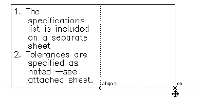
The area resizes and the text is redraws.
9. Explore the text processing functions to become comfortable with the tools, then delete all the text created in this exercise.
• Choose Edit>Select All.
• Press the BACKSPACE (Windows) or the DELETE (Macintosh) key to delete all selections.
Accomplishments
• Entering text
• Changing text characteristics
• Grouping entities
• Specifying a hanging indent
• Making changes to text
• Changing the size of the text area
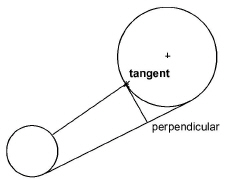
Exercise 3: Tangent and Perpendicular Lines
This exercise explores drawing tangent and perpendicular lines.
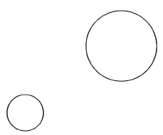
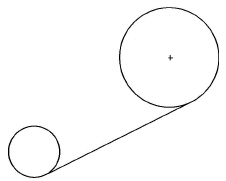
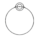
1. Draw two circles like those shown here using a circle tool.
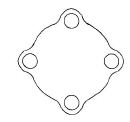
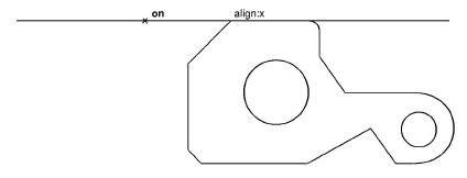
2. Construct a line tangent to the lower edges of both circles.
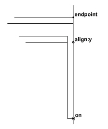
• Click the Single Line tool. The Message Line reads, Single Line: Pick beginning point [Ctrl = Copy previous (Windows) or Option = Copy Previous (Macintosh)].

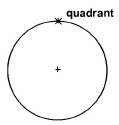
• Move the pointer to the circle on the left until the on notation appears.
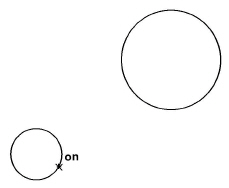
Tech Note: The Drafting Assistant must display on and not other circle notations such as quadrant.
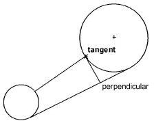
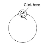
• Drag the pointer away from the circle at approximately a 45° angle until the tangent notation appears as shown in the following graphic. Do not release the mouse button.

• Drag the pointer to the lower edge of the large circle until the tangent notation appears.
Tip: Notice that the dragged line stays tangent to the circle wherever it is dragged.
• Release the mouse button.
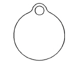
The tangent line is drawn.
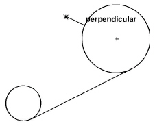
3. Construct a line perpendicular to both circles.
• Press the mouse button when on appears on the large circle.
• Drag directly away from the circle at approximately a 90° angle until the perpendicular notation appears.
• Drag to the left circle until the perpendicular notation appears.
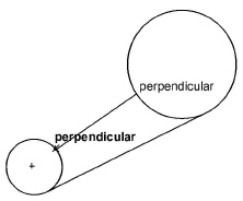
Tip: Tangent and perpendicular lines can be pulled off circles and other lines, as well as ellipses, splines and arcs.
• Release the mouse button.
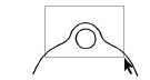
The line is drawn perpendicular to both circles.
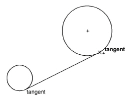
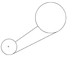
4. Construct a line perpendicular to the lower straight line and tangent to the larger circle.
• Move the pointer to the lower straight line and press the mouse button when on notation appears.
• Drag at a 90° angle from the line to display the perpendicular notation. Do not release the mouse button.

• Drag the new line along the lower straight line to the large circle until tangent appears.
The line is drawn tangent to the large circle and perpendicular to the lower straight line.
5. Save the file.
Accomplishments
• Constructing tangent lines
• Constructing perpendicular lines
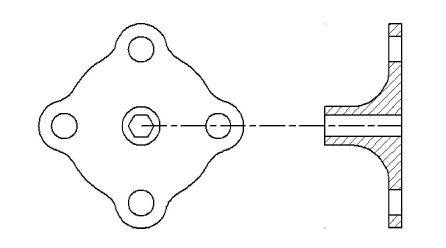
The next four exercises construct a flange with a side view.
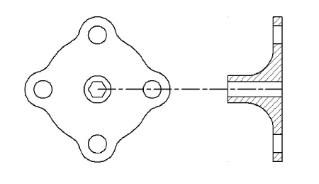
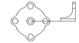
For this exercise, draw a flange 3 inches in diameter containing four 1-inch lugs each with 0.5-inch holes. Center a 0.5-inch octagonal hole in the .75-inch hub of the flange.
1. Open a new document.
2. Choose a different pen style.
• Choose Pen>Style>Visible or right click to show the context menu and choose Style option and then Visible from the drop down menu.
The pen style is now solid, black lines .02 inches wide.
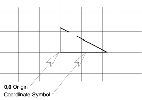
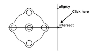
3. Draw a 3-inch circle centered at 0,0.
• Choose Layout>Show Grid or CTRL+G to see the origin.
Tech Note: This step is not necessary. It merely shows the grid and origin point. When the grid is on drawn lines, snap to the divisions on the grid.
The grid appears on the drawing area.
• Choose the Center-Point Circle tool.
• Type 3 in the Status Line and press the TAB key.
• Type 0 and press TAB.
• Type 0 and press ENTER (Windows) or RETURN (Macintosh).
The 3-inch circle is drawn, centered at 0,0.
• Choose Layout>Hide Grid or CTRL+G.
The grid and coordinate symbol disappear.
4. Draw a 0.5-inch lug hole centered at the top of the 3-inch circle.
The Center-Point Circle tool is still the current tool.
• Click on the 12 o’clock quadrant notation.
• Type 0.5 in the Status Line and press ENTER (Windows) or RETURN (Macintosh).
A 0.5-inch circle is drawn, centered on the top of the 3-inch circle.
5. Draw a 1-inch circle with the same center as the .5-inch circle.
• Type 1.0 and press ENTER (Windows) or RETURN (Macintosh).
Another circle is drawn, centered at the same place and with a diameter of 1 inch.

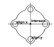
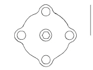
6. Create fillets with the default .25-inch radius where the lug joins the flange.
Tech Note: The Fillet tool is designed to trim lines, arcs and splines, but not circles as time saving measure.
• Click the 2-Entity Fillet tool.

• Hold down the SHIFT key and click between the two curves, as shown by the x in the graphic below.

• Repeat the process on the other side of the lug.
Tech Note: Tangent and perpendicular lines can be pulled off circles and other lines as well as ellipses, splines and arcs.
The fillets are complete.
7. Trim the lug.
• Click the Selection tool.
The last fillet created is still selected.
• Hold down the SHIFT key and click the other (unselected) fillet.
Both fillets are selected to be used as the boundaries for trimming.
• Click the Simple Trim tool in the Trim Tools palette or in the right click context menu.

• Click the bottom of the 1-inch circle and the top of the 3-inch circle.
The circles are trimmed between the fillets.
8. Construct a total of four lugs for the flange.
• Click the Selection tool.
• Drag a fence around all entities that make up the lug.
Tech Note: Only the objects inside the fence are selected.
The lug is selected.
• Choose Edit>Polar Duplicate from the menu or select the icon from the tool palette or from the right click context menu.

The dialog box should be set to rotate 4 objects, with the Center X, Y coordinates set at 0,0.
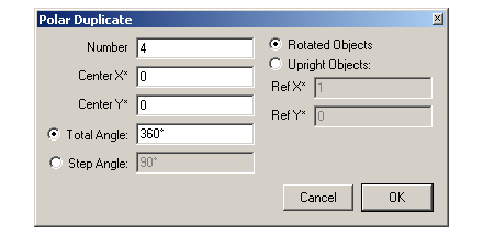
Tech Note: The asterisks next to the Center X and Center Y data fields indicate that a coordinate may be typed in the field or the locations specified with the mouse. To use the mouse, first click the Center X data field. Then click the location for the center on the drawing area.
Tech Note: For this exercise, the default location is 0,0 so don’t enter any entries in this data field.
• Click OK.
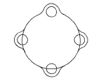
The lug is copied, but the 3-inch circle must be trimmed.
9. Trim the circle inside the copied lugs.
• Use the Selection tool and the SHIFT key to select the fillets for the three copied lugs.
Tech Note: To deselect something, continue holding down the SHIFT key and click again.
• Choose the Simple Trim tool from the Trim Tools palette or from the right click context menu and trim the circle between the fillets.
The lugs are complete.
10. Construct a .75-inch circle in the center of the flange.
• Select the Center-Point Circle tool.
• Move the pointer to display the horizontal construction line through the left bolt hole.
• Display the vertical construction line for the lower bolt hole and click at the intersection of these two construction lines.
• Type .75 and press ENTER (Windows) or RETURN (Macintosh).
11. Add the .5-inch (outside measurement) octagonal hole within the .75-inch hub.
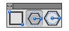
• Select the Inscribed Polygon tool. The Message Line reads, Inscribed Polygon: Pick center of polygon [Ctrl = Copy previous (Windows) or Option = Copy previous (Macintosh)].
Confirm that the Status Line shows the X,Y coordinates as 0,0. If this is not the case, enter 0 into each of these data fields.
• Type .5 in the Diameter data field (do not press ENTER or RETURN).
• Press the TAB key to select the Sides data field.
• Type 8 and press ENTER (Windows) or RETURN (Macintosh).
The octagonal hole is drawn and

the flange is complete.
12. Save the part, naming it flange.
• Choose File>Save.
• Type flange and press ENTER (Windows) or RETURN (Macintosh).
Accomplishments
• Displaying the grid
• Placing geometry at the origin
• Filleting circles
• Making multiple selections
• Trimming unnecessary geometry
• Rotating and copying the lug
• Constructing an inscribed octagon
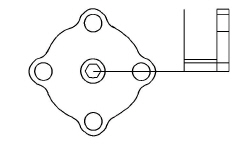
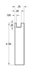
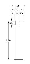
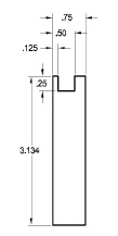
Exercise 5: Constructing a Side View
Create a side view of the flange that is 1.5 inches thick at the hub and .25 inch thick at the lugs.
1. Zoom out from the part.
• Click the Zoom Out tool or scroll the scroll mouse wheel forward.

• Enter .80 in the Status Line.
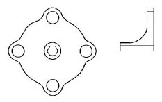
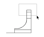
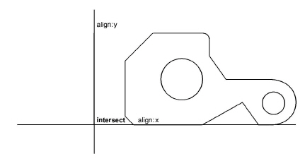
2. Construct a vertical line for the side view that is the same length as the distance from the top of the flange to the center.
• Click the Single Line tool.
• Move the pointer to the top of the flange to display the construction line and move to the right the approximate distance shown below. Click on the construction line.
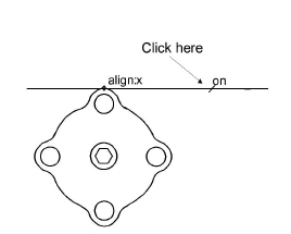
• Move the pointer to the center of the right bolt hole to “awaken” it, then move to the right to display the horizontal construction line. Click at the intersect point of the horizontal and vertical construction lines.
The first vertical line for the side view is drawn.
3. Construct the remaining vertical lines of the side view.
• Click the Parallel Lines tool. The Message Line reads, Parallel Lines: Drag new line off existing line.

• Drag a line to the right of the vertical line in the side view.
• Type 1.25 and press ENTER (Windows) or RETURN (Macintosh).
The parallel line is drawn 1.25 inches to the right of the original line.
• Click the original vertical line.
• Type 1.5 and press ENTER (Windows) or RETURN (Macintosh).
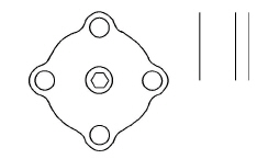
The vertical lines are complete.
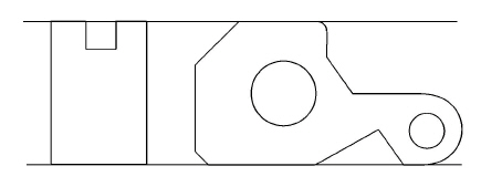
4. Construct the horizontal lines for the side view.
• Select the Single Line tool.
• Draw a horizontal line across the top of the right arm of the side view.

• Continue drawing the horizontal lines aligned with these locations and in the order shown below:
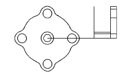
Top of bolt hole
Bottom of bolt hole
Top of hub
Top of octagon
Center of flange
The lines are drawn and the centerline is selected. If it is not, use the Selection tool to select the line from the center of the flange to the side view.
• Choose Pen>Style>Center or right click to show the context menu and click Style option, then choose Center from the drop down menu.
• Choose the Selection tool.
Tip: Use the Stroke commands to zoom. Hold down CTRL+SHIFT keys (Windows) or the z key (Macintosh) and Stroke zoom, drag from the upper left to the lower right across the side view to zoom in. Alternatively select the Zoom In tool and drag a fence around the side view. Also it is possible to scroll backward the mouse scroll wheel to enlarge the view.
Tech Note: If zooming takes you places you didn’t want to go, choose Arrange>Zoom All or double click the mouse scroll wheel and all geometry appears, filling the window.
• Click outside the flange to deselect everything.
• Choose Pen>Style>Visible or right click to show the context menu and click Style option, then choose Visible from the drop down menu.
5. Trim the excess lines.
• Save the drawing in case things don’t go as expected.
• Zoom in on the side view only.
• Select the trim boundary.
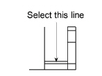
• Trim the vertical line on the left that extends above the selected horizontal line.
The vertical line trims.
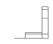
• Trim the vertical line that descends from the inside corner to the centerline
.
The trimming is complete.
• When the drawing looks right, save it again.
Tech Note: If you have had trouble, and the drawing is not right, close this document without saving it. To close without saving, click the Close box icon, then click No when asked if you want to save. Next, choose File>Open and open the flange document again, and repeat Exercise 5
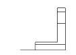
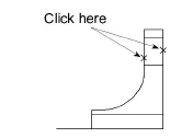
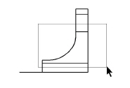
6. Create the hub fillet with a radius of .75 inch.
• Select the 2-Entity Fillet tool.
• Enter .75 in the Radius data field.
• Hold the SHIFT key down and click inside of the corner of the side view.
The fillet is redrawn to a .75-inch radius.
• Zoom out to see the entire flange.
Accomplishments
• Constructing a side view
• Creating parallel lines
• Creating a centerline
• Trimming corners
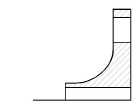
Exercise 6: Advanced Crosshatching
In this exercise crosshatch the side view. Since the side view isn’t a single closed figure, segment some of the lines for the crosshatching to work properly.
1. Zoom in on the side view.
• Scroll backward the mouse scroll wheel.
2. Select all geometry for the side view by dragging a selection fence around the side view.
3. Use the Segment tool to break the vertical lines at the intersection of the horizontal lines. This is necessary to define a closed boundary to crosshatch.
Tip: Use the Tracer tool to select these unsegmented boundaries. Practice both methods of selecting lines.
• In the Trim palette or in the right click context menu, choose the Segment tool. The Message Line reads, Segment: Pick entity [Shift = Select boundary, Ctrl = Current pen (Windows) or Option = Current pen (Macintosh)].

• Click the vertical lines to be segmented.
Tech Note: To understand this process, consider how to create the side view. The right vertical line is a single line which is met by the horizontal lines forming the bolt hole and center hole. Graphite cannot determine the boundary because the horizontal lines touch the vertical lines within the closed figure. In this exercise, segment the boundary lines so they can be selected to form two closed shapes.
• Click the lines representing the center hole.
Tech Note: Although no visable change has occurred, the vertical lines have been segmented into shorter, connected lines.
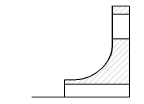
4. Crosshatch the solid sections of the side view.
• Click the Selection tool.
• Click anywhere in the drawing area to deselect the side view.
• Drag a selection fence around the top part of the side view
.
• Hold down the SHIFT key and drag a selection fence around the lower solid section of the side view.
Both sections are selected.
• If the ISO patterns are not already displayed, click the ISO radio button.
The Iron pattern is already selected and displayed in the pattern box.
• Click the Spacing data field.
• Enter .1 and click Apply.
• Close the dialog box.
The side view is crosshatched.
5. Save the part.
Accomplishments
• Segmenting lines
• Crosshatching complex figures
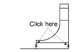
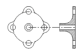
Exercise 7: Mirror Images and Bolt Circles
This exercise demonstrates how to create the bottom half of the side view and add a bolt circle to the front view of the flange.
1. Create the bottom half of the side view.
• Drag a selection fence around the entire side view.
• Select the Mirror tool in the twelfth sub palette of the main tool palette or in the right click context menu. The Message Line reads, Mirror: Pick beginning of reference line [Shift = Select, Ctrl = Copy (Windows) or Option = Copy (Macintosh)].

You are asked to specify a reference line.
• Hold down the CTRL (Windows) or the OPTION (Macintosh) key and click on the centerline at two places in the side view.

Tech Note: CTRL (Windows) or OPTION (Macintosh) plus click causes the transformation tool make a copy and transform the geometry.
Tech Note: Crosshatch patterns are mirrored in shape but the pattern orientation remains the same. To change orientation on cross hatching use Edit Objects.
The side view is complete.
2. Add a bolt circle to the front view.
• Select the Selection tool and click anywhere to deselect the side view.
• Choose Pen>Style>Center or right click to show the context menu and click Style, then choose Center from the drop down menu.
• Select the Center-Point Circle tool.
• Drag from the center of the flange to the center of one of the four bolt holes.
• Use the Selection tool and click in the drawing area to deselect the circle.
• Choose Pen>Style>Visible or right click to show the context menu and click Style, then choose Visible from the drop down menu.
3. Save the part and close the document.
• Close the current Graphite window.
You are asked if you want to save the document.
• Click Yes.
The document saves and its window closes. Other windows may appear if other Graphite documents are open.
Accomplishments
• Creating a mirror image
• Creating a bolt circle
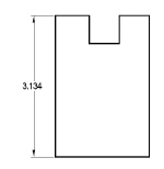
This exercise constructs a side view of the part built previously in the Basic Graphite section, using one of Graphite’s most powerful features, Parametrics. With parametrics, construct geometry in the desired shape and then Graphite automatically redraws the geometry with specific measurements.
1. Begin by opening the part saved earlier.
• Choose File>Open.
• Double-click the filename part1a.
If the file is saved in a different folder or given a different name, select the filename accordingly.
2. Zoom the drawing to see the part and have room for the new construction.
• Choose Arrange>Zoom All or double click the scroll wheel of the mouse.
• In the tool palette, select the Zoom Out tool or scroll forward the mouse scroll wheel.
• Click anywhere on the left side of the part.
3. Hide the dimensions created to make it easier to construct the side view. (Note the placement of the dimensions so that the side view is not built on top of them.)
• Select the Dimension layer.
The Show button toggles to Hide.
• Click Hide.
The dimensions are no longer visible on the drawing.
• Close the dialog box.
4. Construct a side view that represents the final shape; don’t be concerned with proportions or measurements.
• Choose the Pen>Style>Visible or right click to show the context menu and click Style, then choose Visible from the drop down menu.
• Select the Connected Lines tool.
• Drag the pointer over the top endpoint of the 45° line to activate the horizontal construction line from the top of the part, but do not click.
The point on the part activates so that the Drafting Assistant displays a dynamic construction line through it to assist in constructing the side view.
• Move the pointer to the left a short way along the construction and click the first point. Be sure an on notation appears.
• Drag a line to the bottom endpoint of the chamfer to “awaken” a horizontal construction and drag to the left along the construction line until an intersect notation appears.
• Create the shape on the left below, approximating the horizontal measurements.
5. Save the part.
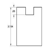
6. Dimension the vertical components of the side view, using baseline dimensions.
• Choose Layout>Layers.
• Select Dimension and click Show.
The Dimension layer appears.
• If necessary, choose Dimension>Show Palette.

• Select the Vertical Base Line Dimension tool. The Message Line reads, Vertical Base Line: Pick first dimension point.
• Select the top-left corner then the bottom-left corner of the side view.
Tip: In this case, since everything is measured from the baseline, select the baseline first, regardless of the proper order for displaying the dimension. This means that the dimension is not displayed in the proper location, but the dimension can be dragged once it appears.
• Drag the dimension to the left so that another dimension can be placed between it and the side view, as shown.
Tech Note: In this example, only the vertical dimension displays its real value—it measures the actual height of the part. Specify the values of the other dimensions.
• Dimension the depth of the notch. Select the bottom of the left side of the notch. (Remember the baseline is already selected.)
• Drag the dimension text to the left between the view and the last vertical dimension.
• Enter .25 in the Status Line and press ENTER (Windows) or RETURN (Macintosh).
Tip: This entry goes into the Text data field on the Status Line, specifying the value needed rather than the current value.
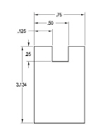
7. Dimension the remaining components of the side view.
• Select the Horizontal Base Line Dimension tool. The Message Line reads, Horizontal Base Line: Pick first dimension point.
Enter the values as shown. By beginning at the left corner, the dimensions will be properly placed.
Tech Note: To correct mistakes, press the BACKSPACE (Windows) or DELETE (Macintosh) key if the dimension is still selected. If it is not selected, select it with the Selection tool and then press the BACKSPACE (Windows) or DELETE (Macintosh) key.
8. Save the part.
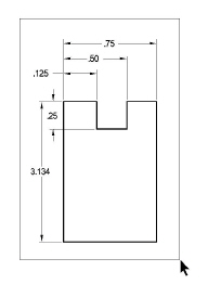
9. Resolve the parametrics for the side view.
• Drag a selection fence around the side view, including the dimensions.
• Choose Edit>Resolve. The Resolve dialog box appears.
• Click the upper-right corner of the side view so that corner stays aligned with the front view.
• Click OK. The part redraws using the new measurements.
10. Move the .125 dimension text to a better location.
• Deselect everything by clicking in an empty space with the Selection tool.
• Select the .125 dimension text.
• Drag the text to the left so that it is outside the extension lines, as shown below.
11. Save the part.
Accomplishments
• Using layers
• Entering specific dimensions
• Resolving parametrics
Exercise 9: Variable Parametrics
This exercise uses parametrics with variables. Using variables, draw a part and then assign different values for the dimensions. In this way recreate the part repeatedly with different specifications.
1. Open a new document.
• Choose File>New.
A new Graphite document opens.
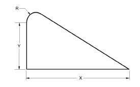
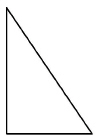
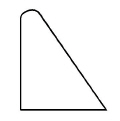
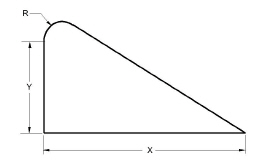
2. Draw the triangle here.
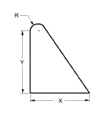
3. Fillet the upper corner of the triangle.
4. Dimension the triangle using variables.
• If the Dimension tool palette is not visible, choose Dimension>Show Palette.
Tip: If the palette obscures the construction, move it by dragging the title bar.
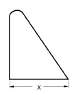
• Select the Horizontal Dimension tool. The Message Line reads, Horizontal: Pick first dimension point.

• Dimension the horizontal line, clicking the right side first.
• Type X in the Status Line and press ENTER (Windows) or RETURN (Macintosh).
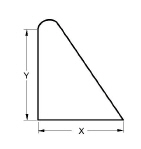
• Select the Vertical Dimension tool. The Message Line reads, Vertical: Pick first dimension point.

• Dimension the left vertical line, clicking the lower endpoint first.
• Type Y in the Status Line and press ENTER (Windows) or RETURN (Macintosh).
• Using the Radial Arrow Out Dimension tool, dimension the radius, using R as the variable.
5. Resolve the geometry to specific dimensions.
• Double-click the Selection tool to select everything.
Tech Note: The next step won’t work if there is extraneous geometry in the document and everything is selected. If that is the case, instead of double-clicking the Selection tool, drag a selection fence around the triangle and its dimensions.
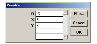
e.
• Type .5 for R and press the TAB key.
• Type 5 for X and press the TAB key.
• Type 2 for Y and click OK.
The geometry is redrawn to the specified dimensions.
6. Save the document in the Symbols folder of Graphite.
• Display the Symbols folder.
• Type Test in the Filename data field.
• Click OK.
The document saves as Test in the Symbols folder.
Tip: With the File>Symbol... menu selection any Graphite document can be brought into a current document as a symbol. Files do not have to be saved in the Symbols folder.
7. Use a symbol.
• Choose New from the File menu.
A new Graphite document displays.
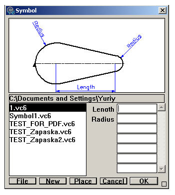
• Choose File>Symbol....
• The Open dialog box appears.
• Select the symbol file to use and click Open.
• The Symbol dialog box appears displaying a preview of the currently selected symbol. All symbol files in that directory appear in the symbols list on the left side of the Symbol Panel.
Tech Note: It is possible to use a text file to fill in parametric dimensions of a symbol. Create a text file with value pairings for each variable and its value. Then load the symbol and click on File in the Symbol Panel. The file automatically fills in the values specified for each dimension.
• Enter a value for each of the parametric dimensions.
• Specify the location and orientation for the symbol.
• In the dialog box, a triangle appears on the geometry to indicate the origin or the located point. Upon clicking, the symbol inserts at the click location, in its original orientation.
• Drag the mouse to indicate the insertion point for the symbol and the direction of the orientation.
• If a location is not specified, scroll to see the symbol.
• Click Place.
• The geometry resolves and appears in the current drawing at the location clicked, sized as specified.
• The symbol geometry is selected to move it to a new location.
• Add regular dimensions if desired.
• To see an enlargement of any part of the symbol within the viewing window, move the pointer to the area of interest and press the mouse button. The enlargement reduces when the mouse button is released.
Tech Note: It is possible to see an enlargement of any portion of the symbol by moving the pointer to the area to be enlarged and pressing the mouse button.
The Symbol box appears with the shape of the selected symbol.
8. Save or discard the documents.
Tech Note: If values cannot be used for the resolution, an error message appears. If this happens, choose Symbol again and enter different values.
Accomplishments
• Dimensioning with variables
• Resolving parametrics
• Creating symbol files
• Using symbols
This exercise creates and edits splines and observes the difference between splines constructed through specific points and those constructed from vectors.
1. Open a new document.
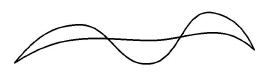
2. Select the Through-Points Spline tool. The Message Line reads, Through-Points Spline: Pick control point [Double-click last point].

3. Click points such as those shown below, double-clicking the
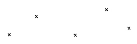
last point.
A NURB spline is drawn through the control points specified.
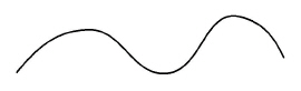
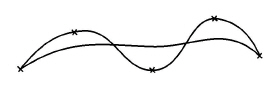
4. Select the Vector Spline tool. The Message Line reads, Vector Spline: Pick control point [Double-click last point].

5. Click the same points (the vertex notation appears at the points clicked for the first spline). A different curve is constructed using the vectors for calculation.
6. Edit the control point in the middle of the original spline.
• Select the original spline.
• Choose Layout>Show Points or right click to show the context menu and choose Show Points option.
The control points and the endpoint slope controls are displayed.
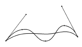
• Select the Lock Spline Control Point tool. The Message Line reads, Lock Spline Control Point: Pick control point.

• Click the control points on both sides of the middle control point, as shown here.
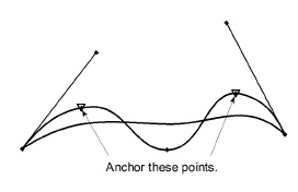
The points are locked.
• Deselect the spline.
• Select the middle control point.
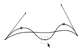
Tech Note: To select this point, choose Edit>Selectable Points and reselect the control point.
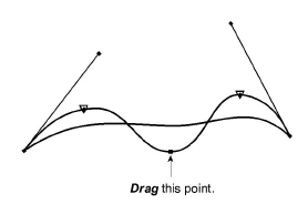
• Drag the middle control point to new locations and observe how the spline is redrawn.
Accomplishments
• Creating a through-points spline
• Creating a vector spline
• Editing splines
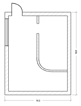
In this exercise use the Smart Wall tool to create a simple architectural drawing, a floor plan with outside measurements of 14 feet by 18 feet.
1. Open a new Graphite document.
2. Set the units to feet.
• Choose Layout>Preferences>Units.
• Click Feet and click OK.
Tech Note: Use different units of measure in the Status Line entries. If the selected units are not feet, be sure to specify the unit such as 2’ for two feet or 2 cm for two centimeters.
3. Create two new layers: one for the interior walls and one for the exterior walls.
• Select Layout>Layers.
The Layers dialog box appears.
• Click New to create another layer.
• Rename the layer by typing Interior walls in the Rename data field and click Rename.
• Click New to create another layer.
• In the Rename data field, rename the layer by typing Exterior walls and click Rename.
• Select Exterior walls and click Set Layer, to make Exterior walls the current layer.
4. Draw the exterior walls.
• In the Line subpalette, select the Smart Wall tool. The Message Line reads, Double Line: Pick start point [Shift = Flip].

• Enter 4'' in the T Status Line data field to indicate walls that are 4 inches thick.
• Drag a horizontal line.
• Enter 14 in the L Status Line data field and press ENTER (Windows) or RETURN (Macintosh).
The line extends off the screen.
Tech Note: Click twice on the down arrow to scroll the horizontal wall downward on the screen.
• Choose Arrange>Zoom All or double click the mouse scroll wheel.

The entire line is visible.
• Press the SHIFT key and drag down vertically from the endpoint of the line at the upper-right corner. (The first graphic below shows the point to select and the second shows what happens while dragging.)
Tech Note: Selecting Layout>Show Points or Show Points option from the right click context menu helps to align the defining points of a wall precisely to the defining points of the previous wall segment.
It is critical to hold down the SHIFT key and drag to construct the wall so that the wall thickness is not added to the length of the first wall.
• Enter 18 and press ENTER (Windows) or RETURN (Macintosh).
A corner is made between the first and second lines, and the second line extends off the screen.
• Choose Arrange>Zoom All or double click the mouse scroll wheel.
• Complete the rectangle, using the SHIFT key while dragging the third wall.

Tech Note: In the Edit Objects dialog box, change the defining axes of selected walls.
5. Change the current work layer with the Work Layer Indicator box at the lower left of the drawing area.
• Click anywhere in the drawing area, to deselect all walls.
• Press the mouse button on the box where the Exterior walls layer is showing and the menu displays.
• Drag to Interior walls.
Interior walls is now the current work layer.
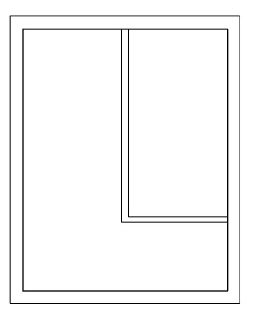
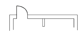
6. Create a drawing like the one below with two interior walls (3 inches thick) which don’t merge with the exterior walls.
• Move the pointer along the inner edge of the upper horizontal wall until the notation midpoint displays.
• Drag a vertical wall segment down about 10 inches long.
• Type 12 in the L (length) Status Line data field.
• Tab to the Thickness Status Line data field and type 3” for the wall thickness and press ENTER (Windows) or RETURN (Macintosh).
The horizontal wall is not merged with the vertical wall segment, since they are not on the same layer.
• Drag a horizontal wall to connect the vertical wall segment with the right vertical exterior wall.
Tech Note: Only walls on the same layer merge.
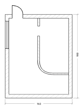
7. Construct a 2-foot hole through the vertical interior wall, 2 feet distant from the upper horizontal wall.
• Move the mouse pointer to the inner left corner of the upper horizontal exterior wall.
• When the endpoint notation displays, hold down the CTRL+SHIFT keys (Windows) or the z key (Macintosh) and drag horizontally toward the center, releasing the mouse button anywhere.
A stroke construction line displays through the inner edge of the upper exterior wall.
• Select the Parallel Lines tool.

• Drag the construction line about 2' towards the middle of the room.
• Enter 2 for the delta distance in the Status Line and press ENTER (Windows) or RETURN (Macintosh).
The parallel line is drawn 2 feet below the upper exterior wall.
• Drag the new construction line about 2' more towards the middle of the room.
• Enter 2 for the delta distance in the Status Line and press ENTER (Windows) or RETURN (Macintosh).
The second parallel line is drawn 2' below the second construction line.
• Select the lower two parallel construction lines with the Selection tool.
• Select the Simple Trim tool from the tool palette or from the right click context menu.

• Click the Simple Trim tool on the vertical interior wall between the two construction lines.
The interior wall trims and the wall segment between the two construction lines deletes.

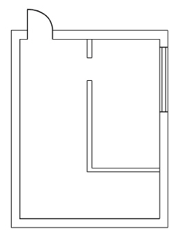
8. Add a 3-foot door beginning at the left 10% point of the upper horizontal exterior wall and extending towards the center.
• Set the layer to Exterior walls by moving the pointer to the Work Layer Indicator box where Interior walls is shown and dragging to the layer.
• Choose Layout>Preferences>Snap.
• Enter 10 for the % Point.
• The Drafting Assistant snaps to 10% points as well as midpoints.
• Navigate to the Symbols>Architect>Plandoor folder on your computer’s hard drive.
• Choose the dsingle.vc6 symbol and click Open.
The Symbol dialog box appears so that the width of the door can be specified.
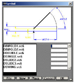
• Enter 90 for the Angle of the door opening and press the TAB key.
• Enter 4'' for the Wall thickness and press the TAB key.
• Enter 3 for the Width of the door.
• Drag the mouse horizontally, starting at the % point on the left side of the upper inside wall, towards the center, and release the mouse button anywhere. The direction of the drag indicates the orientation of the door.
• Click Place.
The wall geometry is redrawn to accommodate the door.
9. Add a 5 foot window beginning at the 10% point of the right wall and extending toward the center.
• Choose File>Symbol and navigate to Architect>planwin (Windows) or Plan Window (Macintosh) folder. Open wcasmnt2.vlm (Windows) or Casement 2 (Macintosh).
• The Symbol dialog box appears to specify the width of the window.
• Enter 4'' (the Wall thickness) and press TAB.
• Enter 5 (the Width of the window).
• Drag the mouse vertically, starting at the % point on the inside wall of the right wall, towards the center, and release the mouse button anywhere.
• Click OK.
The wall geometry is redrawn to accommodate the window.
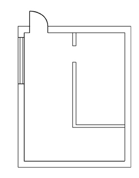
10. Move the window and observe how the walls are automatically reconstructed.
• Select the window and place the pointer on the top left corner of the window.
• Using the Drafting Assistant's dynamic construction line, drag it to the opposite wall.
11. Set the paper size and drawing scale.
• Choose File>Print Setup.
• Select paper size A (or 8.5 x 11 for laser printers). Click OK.
Tech Note: The available paper sizes depend on the printer or plotter specified.
The Drawing Size dialog box displays.
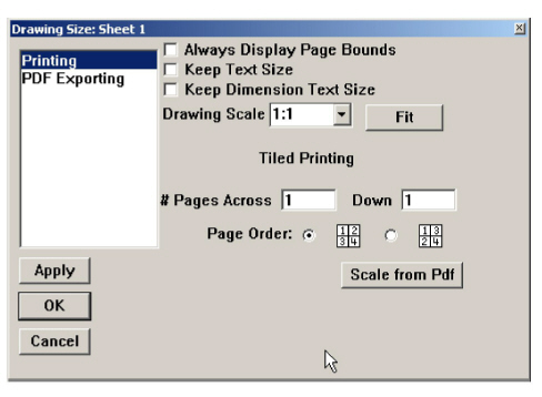
• In the Drawing Scale data field, type 1":2' (this entry is the same as 1:24)
Tech Note: The Scale data field accepts combinations of units of measure.
• Click OK.
12. Segment the exterior walls.
• Select the two symbols (door and window).
• Choose the Segment tool from the tool palette or from the right click context menu.
• With the Segment tool, click the wall segments near the door and the window symbols.
The walls are segmented.
13. Crosshatch the exterior walls.
• Select all visible wall segments of the exterior walls by clicking with the Selection tool.
Tech Note: To crosshatch smart walls containing smart symbols, segment the walls first to create hatch boundaries. Since smart symbols cover only wall segments they can’t be used as hatch boundaries.
The exterior walls are crosshatched.
14. Ungroup the interior walls.
Tech Note: Fillet or chamfer smart walls only if they are ungrouped first. Since smart walls lose their smart features by ungrouping, place all symbols before filleting any smart wall.
• Select the lower vertical and the horizontal interior wall.
• Choose Arrange>Ungroup or right click to show the context menu and choose Ungroup.
Both wall segments are ungrouped and lose their smart features.
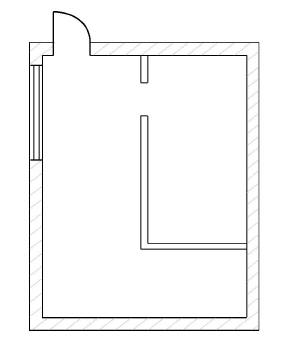
15. Fillet the corner of the two interior wall segments.
• Click the 2-Entity Fillet tool.

• Type 1 in the Status Line for the radius of the fillet.
• Click on the two interior lines of the walls to fillet the two ungrouped walls.
• Type 1.2 in the Status Line for the radius of the fillet for the outer two lines.
• Click on the two exterior lines of the walls to fillet the two ungrouped walls.
The interior walls are filleted.

16. Crosshatch the interior walls.
• Select the upper vertical interior wall segment and all lines building the filleted interior walls.
The Crosshatch dialog box appears.
• Enter -45° for the hatch angle.
• Click OK.
The interior walls are crosshatched.
17. Dimension the sides of the building.
18. Save or discard the file.
Accomplishments
• Using the Smart Wall tool
• Using smart window and door symbols
• Filleting walls
• Crosshatching walls
• Scaling a drawing