


This section investigates Graphite’s advanced drafting procedures, including detail views, drawing to scale and GD&T. In these exercises you will:
• Create a detail view
• Observe dynamic updates in multiple views
• Scale the drawing
• Import a drawing format
• Create a GD&T label
Exercise 1: Creating a Detail View
This exercise create a Detail View. Detail views are additional dynamic cameras showing the same model at either a different angle, or more commonly, at a different scale. Since they are simply a different camera looking at the same model, any changes to a model will show in all detail views.
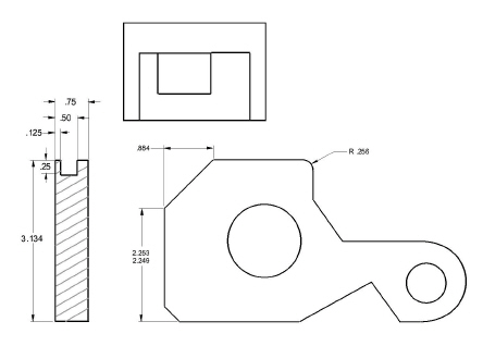
1. Create a detail view of the notch from Exercise 8 in the last chapter of the tutorial, using a 2-to-1 ratio.
• Open the file named part1a.
• Click the Detail View tool on the View Control palette. The Message Line reads, Detail View: Enter view scale then pick first corner of viewing frame.

The Scale data field highlights in the Status Line.

• Type 2.
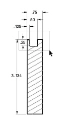
• Drag a frame around the top of the side view, including the notch.
• Drag the frame to a new location.
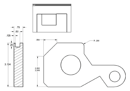
The enlarged geometry appears in the detail view frame.
Tech Note: Note that the detail view is not dimensioned. Crosshatching, dimensions and text are view dependent. They appear only in the view in which they were created according to standard drafting practice.
2. Fillet the right corner of the notch in the detail view and observe that the geometry in the frame is indeed a view of the same part.
• Click the 2-Entity Fillet tool.

• Enter .125.
• Select the two lines that form the lower right corner of the notch in the detail view.
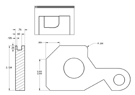
Both the part and the detail view are redrawn with the fillet.
Referral: To know more about working with views, see Chapter 13, “Viewing Geometry,” in the Graphite User Guide.
3. Crosshatch the side view.
• Deselect the view by clicking outside the view with the Selection tool.
• Crosshatch the side view with the Steel crosshatch pattern.
The side view is crosshatched but the detail view is not.
4. Save or discard the file.
Accomplishments
• Creating a detail view
• Observing dynamic updates in multiple views
In this exercise, use the Symbol feature to display a full-scale part, then dimension and scale the part for placement on a standard drawing format. This exercise uses a simple part to demonstrate the procedure used to construct more complex full-scale parts. Drawing at full scale has several advantages, the most important of which is that work can begin without having to specify paper formats or other parameters which would only distract from the design task.
Tip: For help finding the exact location of these files, consult the Knowledgebase in the Support Center of our website at www.ashlar.com. Within the Knowledgebase search specifically for Graphite v10 symbol library locations.
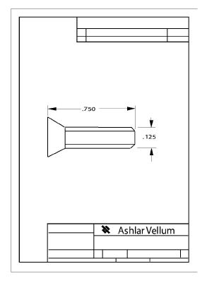
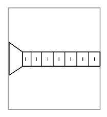
1. Draw a side view of a Phillips-head screw which is .75 inch long and has a thread diameter of .125 inch.
The standard files dialog box appears.
• Navigate to the Symbols folder.
• Navigate to the Fasteners folder.
• Navigate to the Machine screws folder.
• Open the FLATHDPS.VC6 symbol document.
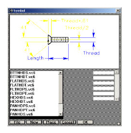
The Symbol dialog panel displays the various types of screws until one is chosen and the measurements of the screw specified.
• Type 0.75 for the Length and press the TAB key.
• Type 0.125 for the Thread and click OK.
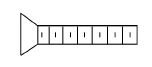
The screw appears.
2. Set the specifications for the paper size.
Tip: The margins on Graphite’s standart layouts are appropriate for most printers and plotters. On the Mac OS X, however, the default “Any Printer” margins are very large and our standart layouts are too big.
• Select the paper size, size A for a plotter or US Letter size for a laser printer.
• Set page orientation to portrait.
3. Set the visual scale of the geometry.
• Click Fit.
Tech Note: The scale is approximately 10:1 but the geometry is visually too large for the page, so reduce the scale to 5:1.
• Enter a scale of 5:1 and click OK.
The size of the geometry is more appropriate for the size of the page boundary.
• Since the geometry looks like the right size for the page, click OK.
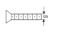
4. Dimension the screw.
• Choose Arrange>Zoom All to display the screw at a larger size. This does not effect the actual measurement.
Tip: Zooming a part does not change its measurements, it magnifies or reduces it to display the specified portion on the screen. In this way it is possible to draw a part full scale, whether it is 100 feet long or 5 millimeters wide.
• Choose the Horizontal Dimension tool.
• Click the opposite ends of the screw.
The dimension displays

• Dimension the diameter of the thread.
5. Place the scaled drawing into a standard A-size drawing format.
• Choose Arrange>Zoom Out or scroll forward the mouse scroll wheel.
• In the Ashlar-Vellum Graphite file, navigate to A Portrait 1 View.vc6 file and click on open.
Tip: For help finding the exact location of these files, consult the Knowledgebase in the Support Center of our website at www.ashlar.com. Within the Knowledgebase search specifically for Graphite v10 layout library locations.
• Be sure to specify Graphite.
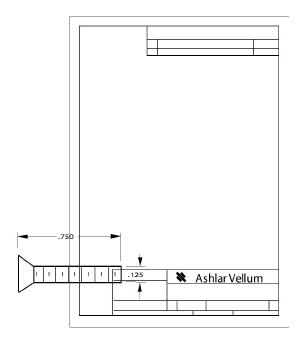
• Click Unscale and OK to import the unscaled drawing format. Unscale unlocks the normal 1:1 scale and uses the current scale during import. Unscale is usually only appropriate for importing layouts.
The format is imported to the sheet and is selected.
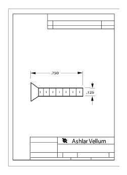
• Drag the format until the screw is properly positioned on it.
Tip: These layouts are just Graphite files and can easily be changed.
6. Use Text>Forms Text... to fill in the drawing layout text. Since the space for the text is quite limited be sure to use initials for names and xx/xx/xx for dates.
7. Plot the drawing.
• If the plotter or printer is set up, to make a copy of this drawing, choose File>Print.
• The drawing is plotted.
8. Save or discard the file, as you wish.
Accomplishments
• Using a symbol
• Scaling a drawing
• Importing a drawing format
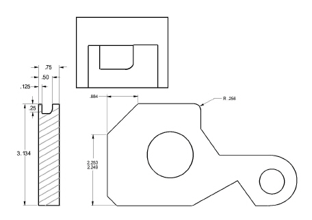
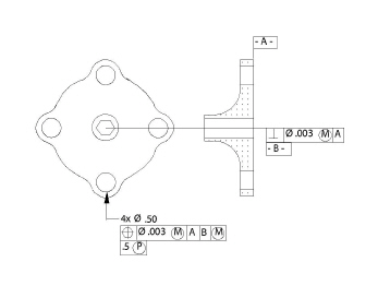
In this exercise add a GD&T label and feature control frames to the flange construction from Chapter 4, “Additional Features.”
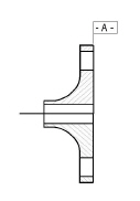
1. Open the flange document showing the flange and the side view.
2. Create a datum label A for the upper-right corner of the side view.
Tip: Move the GD&T dialog box if necessary.
• In the Datum field, type A.
• Select the Witness Line option.
• Click the upper-right corner of the side view to indicate the geometry to which to attach the witness line.
• Click a location on the Drafting Assistant construction line above the corner to place the GD&T label.
3. Create a feature control frame for Perpendicularity for the hub of the side view.
Tech Note: All GD&T text uses the Plotter font so that the sizes meet ANSI standards.
• On Line 1, in the first field, select the Perpendicularity ( ) symbol from the pop-up menu.
• On Line 1, in the second field, select the Diameter (Ø) symbol from the pop-up menu.
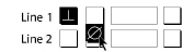
• On Line 1, in the third field, enter .003.
• On Line 1, in the fourth field, select the Maximum Material Condition ( ) symbol from the menu.
• On Line 1, in the fifth field, enter A.
• Change the entry to B in the Datum line.
• Specify Witness Line if it is not already specified.
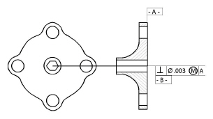
• Click the endpoint of the bottom of the hub in the side view to indicate the position for the witness line.
• Click on the Drafting Assistant’s horizontal construction line to indicate the position of the feature control frame.
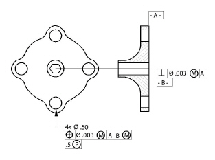
4. Create a feature control frame for true position for the lower lug of the flange.
• In the Label line of the GD&T dialog box, enter 4X Ø .50 to show that the diameter applies to four places.
To get the Ø symbol for Windows press the ALT key and type 0216 on the number keypad of the extended 101 keyboard. To get the Ø symbol for the Macintosh, press SHIFT+OPTION+O.
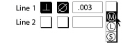
• On Line 1, in the first field, select the Blank symbol at the bottom-right of the pop-up menu to clear the entries in that line.
• Select the True Position symbol from the menu.

• On Line 1, in the second field, select the Diameter (Ø) symbol from the menu.
• On Line 1, in the third field, enter .003.
• On Line 1, in the fourth field, select the Maximum Material Condition ( ) symbol from the menu.
• On Line 1, in the fifth field, enter A.
• Skip the sixth field.
• In the seventh field, enter B.
• In the eighth field, select the Maximum Material Condition ( ) symbol from the menu.
• Enter .5 in the PROJ (Projection) field.
• Delete the entry in the lower Datum line.
• Specify Arrow Line if it is not already specified.
• Drag from the hole of the bottom lug on the flange straight down to indicate the position of the arrow and the label.
• Exit GD&T creation by close the GD&T window or selecting the Selection tool.
5. Edit the second feature control frame.
• Select the second frame created.
• Choose Dimension>GD&T.
• Change the .003 entry to .005.
• Click Edit. The text changes in the frame.
6. Save or discard the file.
Accomplishments
• Creating a GD&T label
• Editing a feature control frame