


Up till now, all the exercises have been two dimensional. This exercise introduces the third dimension. Discover how easy it is to use. All of the tools used in 2D space are used in 3D.
This chapter constructs a wedge die part and then creates a 2D drawing with four views (Top, Front, Right and Trimetric).
Since working in Graphite is a smooth transition from 2D to 3D, it is fine to start the drawing in 2D.
Tip: As your need for 3D becomes more serious check out Ashlar-Vellum's products for 3D modeling, including Cobalt, Xenon and Argon.
Creating the Wireframe Geometry
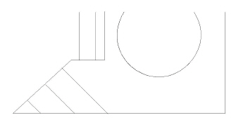
1. Begin with a new document and draw a rectangle. Make it about three times as tall as it is wide. It should be about 3 inches tall.
• Select the Connected Lines tool.

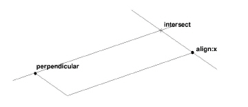
• Draw the first two lines by clicking at points 1, 2 and 3.
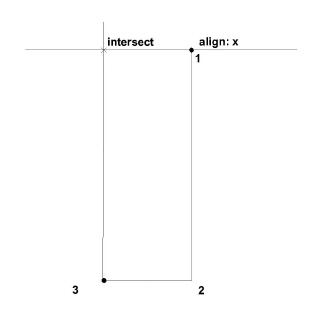
Move up and show the intersect, but don’t click this point yet.
Tip: The Drafting Assistant gives the alignments to complete the shape.
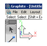
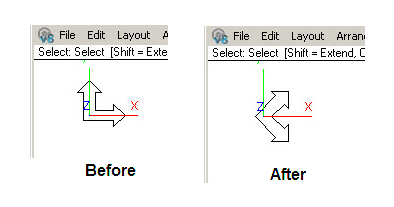
2. Display the Triad and change to a Trimetric view.
This command displays an orientation marker in the corner of the screen.
• Choose Views>Views>Trimetric.
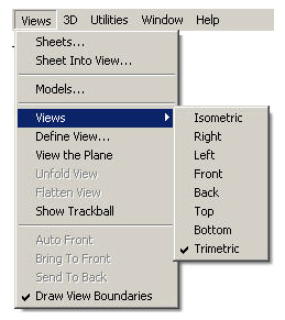
The drawing began in the Top view. Now, the triad has changed to show a new orientation.
Tech Note: Upon starting Graphite, the Top view is automatically selected.
The red one of the three lines is the x-axis, the green one is the y-axis and the blue line is the z-axis.
The black arrows show the work plane. The rectangle has tilted down to match the triad.
Now line up the same intersect point as before, while looking at it from a 3D orientation.
• Click the final two points, to close out the rectangle and double-click at the last point. Continue with the Connected Lines tool.
• Now click on the Scroll Up arrow a few times, to move the rectangle near the bottom of the screen.
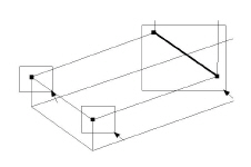
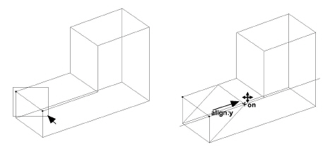
3. Use the Z-Drafting Assistant to draw in the Trimetric view.
• Click on the right-most corner of the rectangle just drawn.
• Position the cursor above the first point of the rectangle, without clicking, to show the Z-Drafting Assistant.
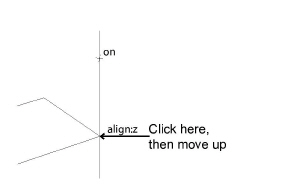
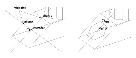
• Move up along the z-construction line and click the end point so the line is about 2/3 as tall as the rectangle is long. Then, without clicking, go down and touch the midpoint of the line, as shown in the graphic on the right.
Tip: Here is the first of many unique features of Graphite. This is the Z-Drafting Assistant. In other words, the Drafting Assistant is working in the third dimension. This provides automatic alignments off the x-axis, the y-axis and the z-axis.
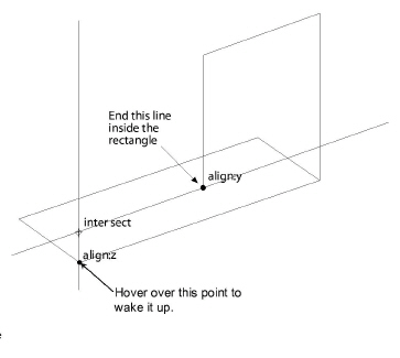
• Come up the z-construction line, and locate the intersect shown.
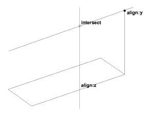
Tip: After the Drafting Assistant displays the intersect, begin moving around in 3D space and create this block by just sketching, and letting the Drafting Assistant find the alignments.
• Click the intersect shown above. Then, move down along the z-axis, and end this line somewhere inside the rectangle as shown by clicking. Then move to the left along the y-axis. Dip down to hover over, but do not click, the lower corner. Then locate the intersect shown here. Click this point.
• Continue with the Connected Lines tool, and pick the five points shown here. Make sure to use the Drafting Assistant construction lines to get the proper alignments. At point 5, double-click to end the line.
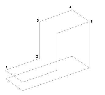
Tip: Picking each of these points, notice how the Drafting Assistant senses where you are and what other geometry is near. It automatically provides all the alignment construction lines necessary to draw this part.
What is shown here is one of the unique features of Graphite; the ability to move around freely in 3D space and pick points, almost like sketching. But having those points end up precisely aligned in all three axes is something that really sets Graphite apart.
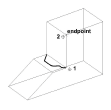
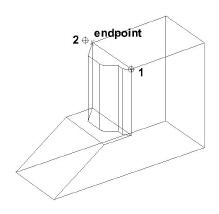
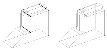
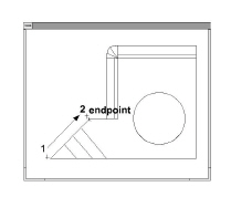
4. Complete the shape of the wedge by moving copies of the selected lines.
• Select the Single Line tool.

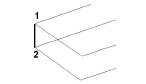
• Draw a single line from point 1 to point 2.
• Select the Selection tool.

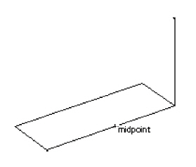
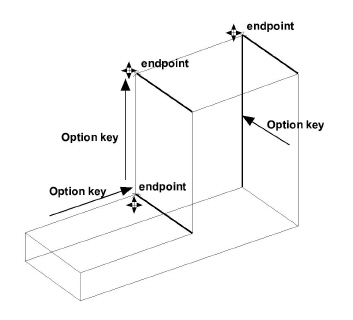
• With the line still selected, place the pointer at point 1. Hold down the CTRL (Windows) or OPTION (Macintosh) key and drag a copy of that line to the endpoint of the top line, as shown below.
Notice that the Drafting Assistant automatically snaps to the endpoints at the start and the end of the move.
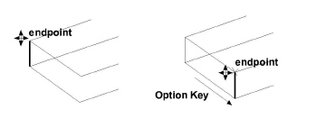
Tech Note: Notice that when the pointer gets near the selected line, it changes from the Selection tool to the 4-Way Move symbol. This moves the selected item(s), as well as makes copies while it is moved.
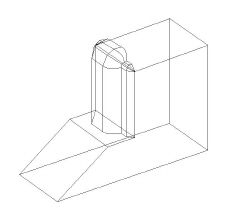
• With the Selection tool, select the line the line above, perpendicular to the line that was just added.
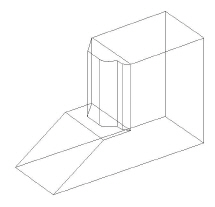
• As before, while the line is still selected, place the pointer at one endpoint, hold down the CTRL (Windows) or the OPTION (Macintosh) key and drag a copy of the line in the y-direction, placing it at the corner of the L. Drag another copy in the z-direction and drop it at the top of the block. Select the long vertical line on the far right side of the part and move a copy of it, as shown. Now, all the lines of the L block should be drawn.
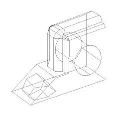
The outline of the Wedge Die is completed. Because of the Drafting Assistant, this process was fast and accurate.
Tip: Do the same thing with some of the other lines. Draw these lines using the Single Line tool, but sometimes it’s easier to copy existing lines.
5. If there is any doubt if this is truly a 3D object, check it with the Trackball. Choose Views>Show Trackball.
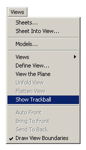
The Trackball/Trackcube comes up on the left side of the screen. For the purposes of this tutorial, it works best to have it on the right, so grab it by its title bar, and move it over to the right.
Tip: With the Trackball/Trackcube rotate the model just by clicking and rolling the ball. The model rotates in real time. Keep in mind, however, that the point of view is changed; the geometry itself remains fixed in model space.
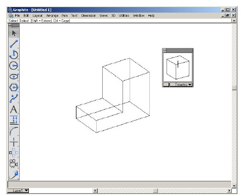
• Rotate the model using the Trackball/Trackcube. Notice that the Triad appears at the center of rotation and displays the orientation of the axes as the model is turning.
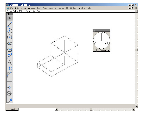
Tip: The button in the Trackball next to the view name changes its display style to cube and sphere.
6. Change the view orientation.
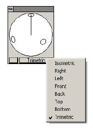
• Choose any view, such as Right or Top, by selecting each view from the pull-down menu on the bottom panel of the Trackball.
To continue with the tutorial, select Trimetric from the pop-up menu on the Trackball.
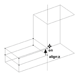
7. Modify the design intuitively in 3D.
• Hold down the SHIFT key and drag three selection fences around the four points shown to select these points. (The one short line in the big fence will also be selected.)
• Release the SHIFT key. Grab one of the points (the pointer will change to the Four Way Move cursor) and drag it vertically. Make sure align:z is seen at the bottom point when starting to move upward.
Tip: One of the great features of Graphite is the ability to modify the design easily in 3D. For example, to make this bottom area about twice as thick as it is now, select these points, and then move this face straight up until it is where it is desired. The Drafting Assistant constrains this movement along the z-axis.
Make the bottom block approximately twice as thick as it was originally.
• In each of the examples below, use the SHIFT key and drag the selection fences shown to select the appropriate points. Then drag one of the points to stretch the part. (Skip this exercise if desired.)
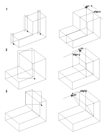
• Choose Undo three times to get the part back to how it looked before the stretch exercises in the previous graphic (skip this if those exercises were skipped). The bottom of the block should be twice as thick as when it was originally drawn.
Tech Note: Graphite has unlimited levels of Undo. To specify the number of Undos when right mouse clicking in empty screen space, select Undo... and specify the number.
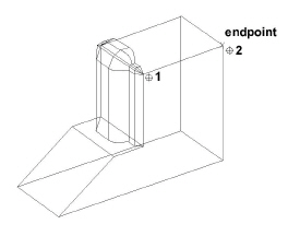
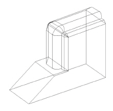
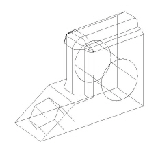
• Regardless of whether the steps on the previous page were done, make sure to do the next one. This step is part of the actual shape of the finished part. Select the two points shown in the graphic and stretch the shelf back along the y-axis (stretch it two-thirds of the way back as pictured here). As part of the design, create a wedge-shaped front.
8. Put a molded face on the front.
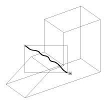
• Do a Stroke-Zoom. Hold down the CTRL+SHIFT keys (Windows) or the z key (Macintosh), and drag the rectangle shown, from upper left to lower right.
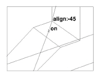
• Pick the Connected Lines tool and draw the line shown, going about two-thirds of the way across the width of the face. Make sure the words align:-45 and on are displayed before the second point is clicked.
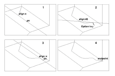
• Finish the contour by drawing the lines and the arc, as shown. In frame 2, hold down the CTRL (Windows) or OPTION (Macintosh) key to temporarily get the Arc tool. Make sure that the words align:45 and on are displayed before clicking the second point.
Tip: Using the Drafting Assistant, construction lines are easily drawn. Hold the CTRL (Windows) or OPTION (Macintosh) key to get the temporary Arc tool.
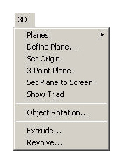
9. Finish the contour by first extruding it up, then by revolving it around the corner of the block, and finally by extruding it along the top face of the block.
• Select Arrange>Zoom All.
• Select Views>Hide Trackball.
• Select the five just drawn lines of the contour (if they are not already selected).
• Select 3D>Extrude.
The Extrude dialog box appears
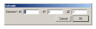
.
Tip: The Extrude dialog box can be moved by grabbing its title bar and dragging it to a new location.
The Extrude function is one of the most important features in Graphite. By entering a set of numbers in the three data fields it is possible to extrude along the vertical line of the face, even if it is currently unknown how far it is or in what direction.
With Graphite, this is easy. Notice the asterisk in the dialog box. The asterisk means, “use the cursor to enter values.”
• Put the bulls-eye cursor on the bottom of the vertical line of the face and drag up to the top of the line, then
release.
Tech Note: One of the important features that is unique to Graphite is the ability to drag from one point to another, and have the values appear in the right data fields.
A number equal to the distance of that drag appears in the dz data field, replacing the –1 that was there.
• Click OK.
The extruded objects appear.
• Now select the same five contour objects, but select the ones at the top of the extrusion. These objects are about to be revolved around the corner of the block.
The Revolve dialog box appears.
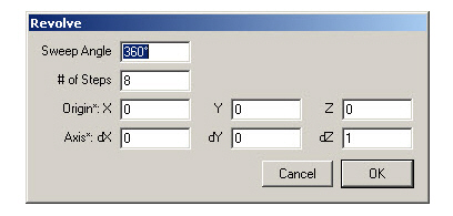
Now take this contour and sweep it 90 degrees, using the corner of the block as the axis of revolution. Knowing this, type 90 into the Sweep Angle data field. Use 4 divisions for the # of Steps. There is an asterisk again in the remaining six data fields, which means, “use the cursor to enter values.” Define the axis of revolution to be from point 1 to point 2.
Tech Note: Indicate how many copies should be placed within the Sweep Angle with the # of Steps.
• Type 90 in the Sweep Angle data field.
• Type 4 in the # of Steps data field.
• Press TAB to move the cursor into one of the data fields for the Origin.
• Define the Axis of Revolution by dragging from endpoint 1 to endpoint 2 as illustrated below. Dragging in the opposite direction, the contour sweeps in the opposite direction.
When releasing the mouse, the data fields for Origin and Axis fill with a series of numbers.
Graphite automatically filled in the numbers for the axis and direction of revolution.
• Click OK.
Graphite builds the sweep.
• Select the five contour objects at the end of the sweep.
• To specify the length and direction for the extrusion, drag from endpoint 1 to endpoint 2 as shown below.
• Click OK.
The contoured face is finished.
10. The extrude operation has created some geometry that makes some of the old lines inappropriate. Select these lines and delete them to clean up the drawing.
• Select the three lines shown by SHIFT-clicking on them, and then delete them.
Tip: At this point get the Trackball out and rotate the part to see it from various angles.
11. The next step is to put a hole on the front face of the wedge and extrude it through the part. By doing so, the concept of Work Planes will be introduced.
Right now, looking at the Triad notice that the Work Plane is parallel to the bottom of the Wedge Die. If you were to draw a circle, it would draw in that orientation. The desired orientation, however, is a circle that stands up along the right face. The work plane must be changed to accomplish this.
Notice that prior to releasing the mouse button, the current Plane was Top or World (indicated by a check mark). Once the mouse button is released, the Triad changes to reflect the new work plane.
• Select the Center-Point Circle tool.

• Touch the midpoint of both the right side and the top edge of the front face to awaken these points. The Drafting Assistant now offers construction lines off of each point.
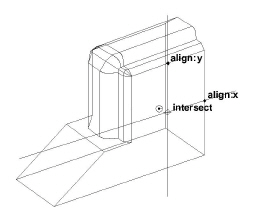
Tip: Use the Trackball to rotate the part to make it easier to see the midpoints of the lines on the right side face.
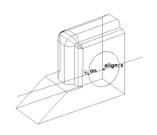
• Go to where the Drafting Assistant shows the intersect of the two alignments and drag the circle along the face (the center of the circle is placed at the intersect). Release the mouse button when the circle is approximately the size shown.
• While the circle is still active, select Arrange>Divide.
The Divide dialog box appears.
• Make # of pieces equal to 4, and deselect the Show Points option.
• Click OK.
Tech Note: Dividing the circle results in four extrusion lines (instead of one). The extra extrusion lines make it easier to visualize the extrusion.
The circle is now divided into 4 arcs. The circle flashes to show that the divide operation executed.
• Select 3D>Extrude.
• Drag from endpoint 1 to endpoint 2.
This defines the distance and direction the circle to be extruded.
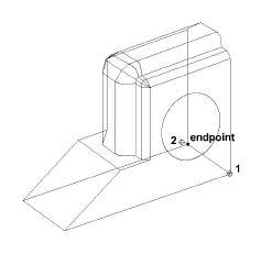
• Click OK.
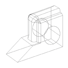
The circle extrudes with four extrusion lines.
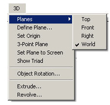
12. The next step is to put a hexagon on the sloped face. This is a good exercise because it shows how Graphite deals with non-orthogonal planes. To draw anything directly on a sloped face, it is logical that the work plane should be set to match it, but looking at the 3D>Planes submenu none of the choices are appropriate (Top, Front, Right and World). For this operation it is necessary to define a new plane.
The Message Line asks for three specific things: the origin, the positive x direction, and the positive y-direction.
Tech Note: Use the Define Plane command only if that plane orientation will be used more than once.
• Click first at endpoint 1 for the origin, then at endpoint 2 for the positive x-direction, and finally at endpoint 3 for the positive y-direction as shown in the drawing below.
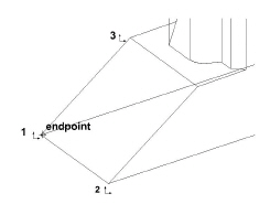
The Triad changes to indicate that the current work plane now matches the sloped face.
Now that the work plane is correctly oriented, draw the hexagon.
• Select the Circumscribed Polygon tool. The Message Line reads, Circumscribed Polygon: Pick center of polygon [Ctrl = Copy Previous (Windows) or Option = Copy Previous (Macintosh)].

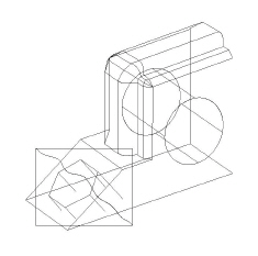
• Touch the two midpoints shown to awaken them and let the Drafting Assistant indicate where the intersect is located. This point will be the center of the hexagon. Drag the second point straight up, and the hexagon is placed onto this sloped face. Release the mouse button when the hexagon is similar to the drawing below.
13. Now extrude the hexagon through the part, perpendicular to the face.
• Select 3D>Extrude.
• Drag one of the points beyond the bottom of the part along the z-direction. Take the extrusion well below the part and release the mouse button. Make sure align:z is displayed so that the extrusion is perpendicular to the work plane.
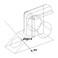
• C lick OK.
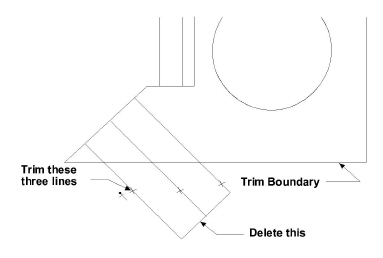
14. The extrusion is extended beyond the base. Use the Simple Trim tool to cut off the excess.
• Change the view to Right (either use the pop-up menu on the Trackball or Views>Views>Right).
• Use the Selection tool to select the bottom line of the part. This acts as a trim boundary.
• Select the Simple Trim tool.

• Click on the extrusion lines that extend below the bottom of the part.
There should be two lines on top of each other in each location, so click twice on each line.
• Select and delete the lower hexagon.
Tech Note: The Simple Trim tool works exactly as it did in 2D, except now it is working on a 3D part. This is great because it is like trimming to a surface.
The hexagon trims to the bottom edge of the part.
• Go back to the Trimetric view.
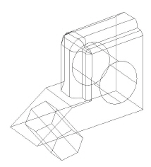
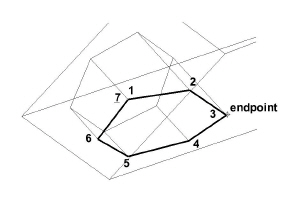
15. Draw the projected hexagon on the bottom surface of the wedge.
• Execute a Stroke-Zoom. Hold down the CTRL+SHIFT keys (Windows) or the z key (Macintosh) and drag a diagonal window from upper left to lower right, as shown.
• Using the Connected Lines tool, connect each of the six endpoints to finish the hexagon hole along the bottom of the part. Double-click at the last point (point 7) to end the connected line.
• Choose Arrange>Zoom Previous to get back to the previous zoom. Hold down the CTRL+SHIFT keys (Windows) or the z key (Macintosh) and drag a diagonal window from lower right to upper left.
16. Save the view.
• It is a good exercise to save custom views. Set the view to Isometric. Rotate it slightly using the trackball and then save the new view. To do this, choose Views>Define View. Click New, and then OK. This will create a new view called View 1. Switch back and forth between this and other views. For the purposes of the rest of the tutorial, it is best to switch the work plane back to World and the view back to Trimetric.
The part is finished! But the tutorial is not done yet. So read on.
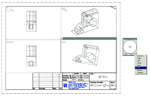
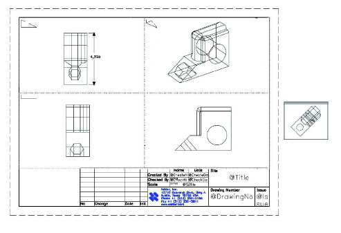
17. Place this part into a 2D drawing with four views (Top, Front, Right, and Trimetric). In Graphite all it takes is one command.
• Select Arrange>Zoom All. Leave the part in the Trimetric view.
• Select Views>Sheet Into View.
The following dialog box appears:
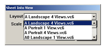
Specify a layout and viewing scale for the original model. There are many choices in this menu including different variations of view arrangements, surrounded by a border and title block. These choices are user definable.
• Select A Landscape 4 View.vc6. Set the Scale to .75.
• When finished, click OK.
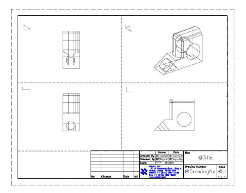
• Select Arrange>Zoom All.
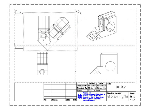
With just one command the 3D wireframe model becomes a layout for a 2D drawing. It has the four views, a title block, and a border. It doesn’t get any easier than this.
Tip: If all of the wedge die is not visable in each view, don't worry. The next step shows how to modify the scale.
18. Edit the view windows.
If a drawing unlike previous illustration appears, such as one where the part is too small or too large in each of the views, modify the scale of each of the four views.
If the drawing looks fine, then skip the next four steps.
• Activate one of the views by clicking on it.
• Open the pull-down menu from the upper left corner of the view boundary.
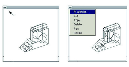
• Select Properties from the pull-down menu.
• Modify the scale to make the part show up in the view more clearly. In this case, since the part is too small at .75 scale, perhaps entering a scale of 1.5 would work better. Find the scale that works well, then make sure to enter the same value for all four of the views.
Use the Trackball to rotate any of the views to a nonstandard orientation.
• Select Views>Show Trackball.
• Click in the Top view window to make it active. (Its title bar will display.)
• Rotate the model in that view by dragging on the Trackball. It is possible to make any of the four views display any custom view. (Rotate the Right view window next.)
• While the Right view window is still active, pick Right from the Trackball pull-down menu. Click on the Top view window to activate it, and select Top from the Trackball menu to put it back to its orthogonal projection.
• Select Arrange>Zoom Out with the SHIFT key (Windows) or CONTROL (Macintosh) pressed down.
• Select Pan in the pull-down menu for the Top view window. The cursor changes to a mover hand icon.
• Drag the wedge to the upper left corner of the view window.
• To finish, drag the lower right corner of the view.
Drag it up, to reduce the size of the view.
• Drag the title bar of the new view and move it into a clean area.
Set the right view to its original size and position.
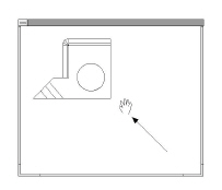
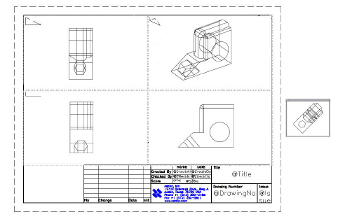
19. Create an unfolded view.
A common drafting operation is to create a view on the drawing that looks straight at a specified face, much like the Projected View problem from high school drafting class.
In Graphite, activate the view, and unfold it.
• Click on the Right view window to activate it.
The message line reads, “Pick start of fold line.”
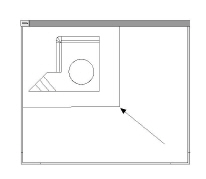
• Drag the mouse button from endpoint 1 to endpoint 2.
• When the mouse button is released, a new view appears on the drawing. (Note: it may appear below the current drawing, requiring you to scroll down, or Zoom All to see it).
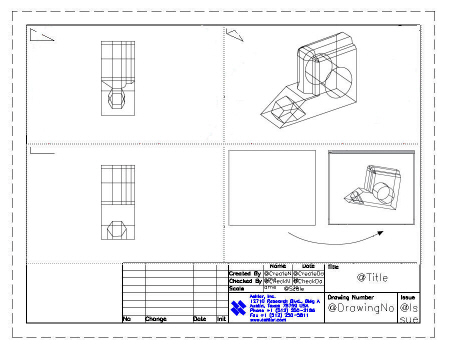
• Resize the unfolded view, Drag its title bar and move it to a clean area.
20. Dimension the part.
• Select Dimension>Show Palette.
The Dimension tool palette appears.
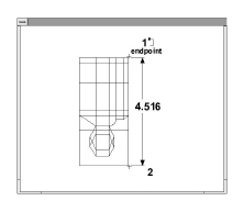
• Select the Vertical Dimension tool.
• Click in the Top view window to activate it.
• Click on the right side of the part from top to bottom to make the dimension appear. Change its font size to make it readable.
Tech Note: During dimensioning pay attention to the Triad. The dimensions work only on the current x-y-plane. A good trick is to pick Set Plane to Screen from the 3D menu. The Triad appears flat in all five views now. All dimensions work as if in a 2D-drawing.
The five views that appear here are dynamic. The dimension object that was just placed, however, appears only in the one view, because these views are smart. Dimensions show only in the view in which they are placed. The same is true for Crosshatching and Text.
21. Print the drawing.
• Hide the Trackball, the Triad and the Dimension palette.
• Deselect view boundaries (Views>Draw View Boundaries).
• Select File>Print Setup and prepare the page settings for the paper and printer.
This should match the layout chosen.
• Be sure to set the scale in the Layout>Drawing Size to 1:1.
• Select File>Print.
Accomplishments
• Creating a 3D wedge die
• Creating 2D drawings