


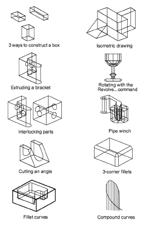
More 3D Shapes
The exercises in this chapter will provide greater familiarity and comfort in creating geometry in 3D. They include:
Tips: If you are left-handed and your mouse has more than one button, you can change the functionality to the right mouse button. Make this change in the Control Panel of Windows.
Exercise 1: Three Ways to Construct a Box
This exercise explores three methods to draw boxes. In each case use the Z-Drafting Assistant to draw the figure.
Method 1
1. Draw a box using the Z-Drafting Assistant.

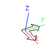
The Triad appears in the upper-left corner of the screen.
Tech Note: The Triad shows the orientation of the work plane, and since the sheet and the work plane are the same, the Triad shows the orientation you are seeing.
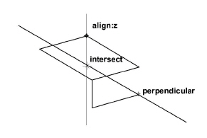
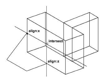
In the Trimetric view with the Top work plane, the Drafting Assistant displays the “vertical” align z notation.
• Choose Views>Views>Trimetric or choose Views option from the right click context menu and then click Trimetric.

The view rotates to the trimetric orientation.
• In the Line tool subpalette, select the Connected Lines tool.
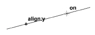
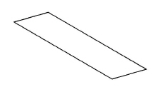
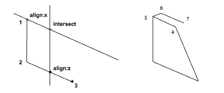
• Begin the first line, dragging toward the upper right along the y axis as displayed by the Drafting Assistant.
• Draw the second line segment on the x-axis.
The x-axis displays as perpendicular to the y-axis.
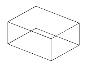
• Draw the next segment to the intersect as shown below.
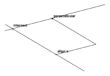
• Complete the rectangle. Don’t double-click when the rectangle is complete.
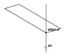
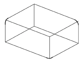
• Extend the rectangle along the align:z construction line, clicking the lower corner, as shown.
• Move the pointer to display the intersect point as shown, and click.
• Click the next intersect point as shown.
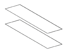
• Continue drawing, double-clicking when the second rectangle is complete.
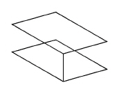
• Use the Single Line tool to connect the corners of the rectangles.
The Trimetric sketch is complete.
2. Rotate this box to observe that it is a 3D model.
• Choose Views>Show Trackball.
The Trackball/Trackcube displays.
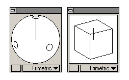
• Drag on the Trackball/Trackcube.
The work plane Triad displays in the center of the screen as the Trackball is dragged, and the box being drawn rotates as you drag on the Trackball.
Method 2
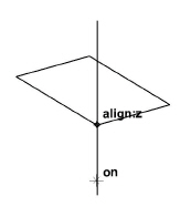
1. On the same drawing area, use the Move tool to create a box.
• Rotate the view to Trimetric, by choosing Trimetric from the Trackball pop-up menu.
• Create another rectangle.
• If the rectangle is not selected, select it.
• In the tool palette or in the right click context menu, choose the Move tool. The Message Line reads, Move: Pick beginning reference point [Shift = Select, Ctrl = Copy (Windows) or Option = Copy (Macintosh)].

• Hold down the CTRL (Windows) or the OPTION (Macintosh) key.
If the CTRL (Windows) or OPTION (Macintosh) key is not held down, the selected object is simply moved while the next two steps.
• Click the front corner of the rectangle for the beginning reference point.
Tech Note: By holding down the CTRL (Windows) or the OPTION (Macintosh) key during this operation, a copy moves to the new location.
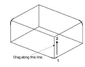
• Indicate the ending reference point by moving the pointer down until the align:z notation appears, and click when the pointer is about an inch from the corner.
• Use the Single Line tool to connect the corners.
Method 3
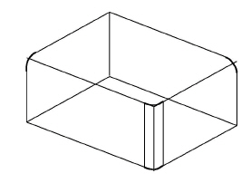
1. On the same drawing area with the view rotated to Trimetric, use the Extrude command to create a box.
• Create another rectangle.
• Select the lines of the rectangle, if they are not already selected.
• Type –2 in the Z data field.
• Click OK.
2. Manually rotate the view with the Trackball and observe how the models
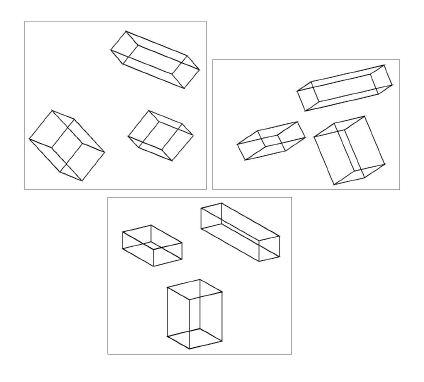
move.
3. Observe the standard views of the models; Isometric, Right, Front, Top and Trimetric.
• Select each of the views from the Trackball pop-up menu, one at a time.
4. Delete all three boxes.
Tip: The three methods used in this exercise are quite simple. While one method may seem to be more appropriate when constructing a particular box, by gaining proficiency in 3D modeling, you’ll find uses for all three methods.
• In the tool palette, double-click the Selection tool.
All geometry is selected.
• Press the BACKSPACE (Windows) or DELETE (Macintosh) key or choose the Delete option in the right click context menu.
All geometry is deleted.
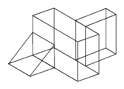
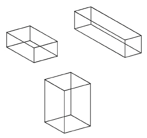
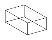
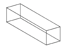
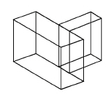
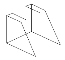
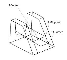
This exercise explores the Drafting Assistant, working along the z axis further by drawing the figure below. Observe the snap points and construction lines which aid in creating isometric drawings.
1. Set the view to Trimetric.
Tech Note: Because isometric views have such a strict angle of view lines often overlap and are difficult to see. We recommend drawing in the trimetric view then changing to isometric as needed.
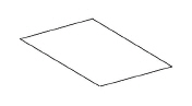
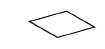
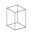
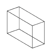
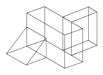
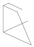
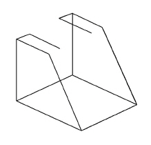
2. Draw the rectangular cube shown at the right, using whatever method.
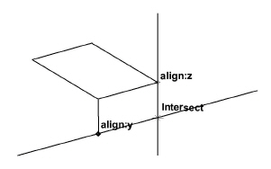
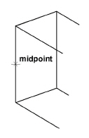
3. Draw the rectangular block adjacent to and aligned at the midpoint of the back face of the first block.
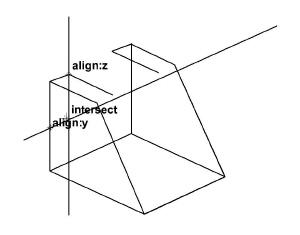
• Use the Connected Lines tool and begin at the midpoint of the upper line.
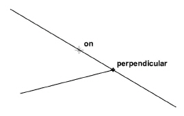
• Observing the align:z and perpendicular notations, begin the construction in the order shown below.
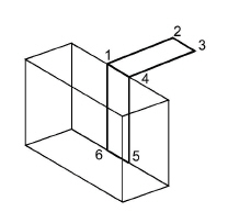
• Double-click at the first location to end this part of the construction.
Tech Note: Remember that it’s possible to press the ESC key to backtrack while drawing with the Connected Lines tool.
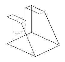
• Complete the block using the Connected Lines and the Single Line tools.
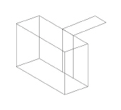
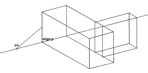
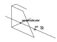
4. Construct a ramp at the midpoint of each side of the rectangle at the front of the first block.
• Use the Connected Lines tool and begin at the midpoint of the left side of the first block.
Tech Note: To snap to a particular point, such as the midpoint shown here, the Z-Drafting Assistant snaps back and forth between snap points in close proximity. To snap to the midpoint, move the pointer until the notations are snapping, and with the mouse button still down, press the m key (for midpoint) on the keyboard.
• Draw the lines as shown in the following illustrations.
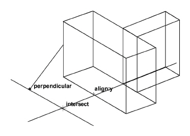
If it is difficult to get the Drafting Assistant to snap to certain location, it may be because the view orientation puts the geometry too close to other geometry. Try rotating the view slightly with the Trackball.
5. Save the drawing, and close the document.
• Choose File>Save.
• Name the drawing.
• Choose File>Close.
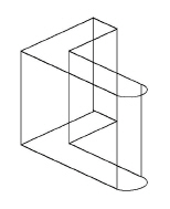
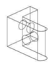
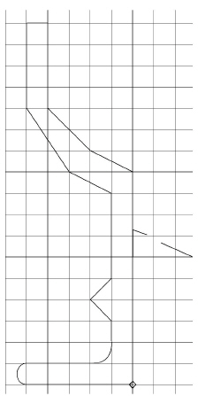
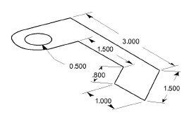
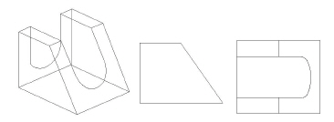
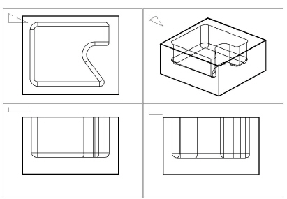
In this exercise, use the Extrude command to draw the bracket below. Extrusions begin by drawing a figure in 2D on the x,y plane and then extruding it in the z-direction. Once an object is created, rotate it or move the work plane to add detail.
1. Open a new document.
2. Draw the 2D outline of the L-bracket, as illustrated, using the measurements provided.
To make the arc segment, hold down the CTRL (Windows) or OPTION (Macintosh) key when clicking the location of the endpoint. Hint: Start at the upper-left corner of the bracket.
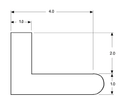
This view of the model is considered the Top view.
3. Extrude the L-shape into a 3D bracket that is 3 inches wide.
Tech Note: If the computer screen represents the x,y plane, then the positive z-direction is coming out towards you. Therefore, to make the apparent depth go into the monitor, enter a negative z-value.
• Select the geometry if it isn’t already selected.
• Choose 3D>Extrude.
• Type –3 for the Z data field and click OK.
The part extrudes, but its depth is not seen because you are looking straight at the x,y plane.
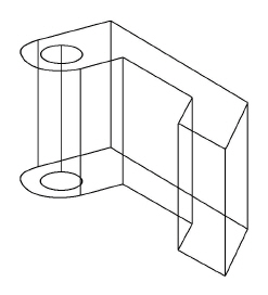
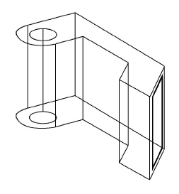
4. Rotate the view orientation to the Trimetric view.
Tip: It is possible to rotate the view manually so that none of the lines overlap.
Tech Note: To begin drawing without doing Step 5, the geometry would be drawn on the x,y plane of the Top view. Move the work plane in order to draw on the front face of the bracket.
Display the Triad if to see the orientation of the work plane.
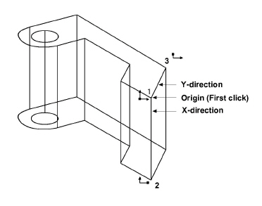
5. Move the work plane.
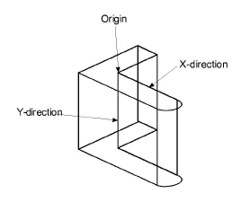
• As illustrated on the right, click the origin, the x-direction, and the y-direction. The Message Line displays instructions.
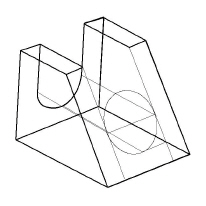
6. Create a one-inch hole at the intersection of the midpoint construction lines of the bracket’s front view. Rotate the bracket to get access to the lines that need to be used.
• Brush over the midpoints of the two lines to a waken them.
• Use the Center-Point Circle tool to draw the circle, centered at the middle of the bracket arm.
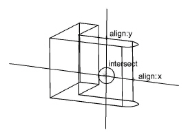
• Type 1.0 and press ENTER (Windows) or RETURN (Macintosh).
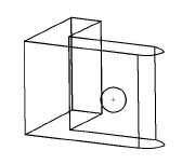
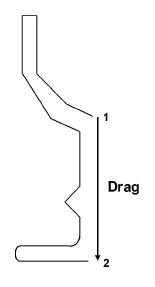
7. Extrude the circle through the thickness of the bracket.
• Choose 3D>Extrude.
• Drag from endpoint 1 to endpoint 2, as noted below, to indicate the direction and length of the extrusion. When releasing the mouse, the values are automatically entered in the data fields.
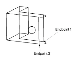
• Click OK. The hole extrudes.
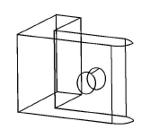
8. Add a hole in the center of the other arm of the bracket.
• Choose 3D>Planes>Right to reset the work plane.
• Draw the circle using the intersect point of the midpoints.
• Extrude the circle as in the last step, using the thickness of this bracket arm.
9. Save the bracket for use in the next exercise.
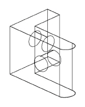
Exercise 4: Interlocking Parts
This exercise uses layers to construct interlocking parts with precise hole alignment.
1. If necessary, open the bracket file saved in the last exercise.
2. Enlarge the bracket to fill the screen and select the lines and circles highlighted in bold in the image below. These lines and circles will be used as the basis for building the mating cube.
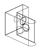
Tech Note: This geometry represents the mating surfaces of the two parts.
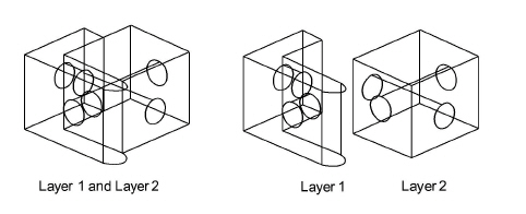
3. Move copies of the selected lines and circles to a new layer.
• Choose Layout>Layers.
• Click New.
Layer 2 is added to the list.
• Click Set Layer.
Layer 2 becomes the work layer.
• In the tool palette or in the right click context menu, click the Move tool.
• Hold down the CTRL (Windows) or the OPTION (Macintosh) key and click any endpoint on the selected geometry.
• Click the same endpoint again.
The selected geometry is copied at the same location; two sets of geometry now exist, both on Layer 1, but only one of the copies remains highlighted (selected).
• Select Edit>Edit Objects or choose the Edit Objects option from the right click context menu.
• Change the Layer entry from Layer 1 to Layer 2.
• Click Apply.
The duplicate (selected) geometry is now on Layer 2.
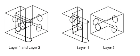
4. Hide Layer 1.
• Click Layer 1 in the list box of the Layers dialog box.
• Click Hide.
The geometry on Layer 1 is hidden, and Layer 2 is still the work layer.
5. Complete the interlocking piece.
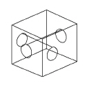
6. Use Show and Hide Layers to display these components of the interlocking model.
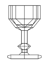
This exercise draws a goblet using the Revolve command. Begin by drawing half of a 2D object touching the revolutional axis.
1. Open a New document.
2. Draw half of a goblet along the vertical axis.
• Choose Layout>Show Grid or use the CTRL+G short cut.
• Draw the outline as shown below.
3. Rotate the half-object around the vertical axis.
• If the geometry is not selected, select it.
• Choose 3D>Revolve.
• Click the Origin data field.
• Drag to indicate the beginning and end of the revolutional axis.
• The default number of steps listed is 8.
• Click OK.
As defined in the Revolve dialog box, the outline revolves 360° through the number of steps entered to make a 3-dimensional goblet.
4. Rotate the view to get a better 3D angle.
5. Save the drawing.
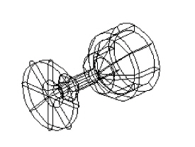
Additional Exercise
Using circles and the Revolve command, create images such as those illustrated below.
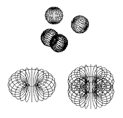
Also practice 180° revolutions to understand how the right hand rule is applied while defining the axis of revolution.
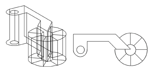
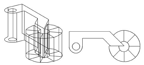
This exercise puts all the 3D modeling methods together to draw a pipe winch for an oil rig.
1. Open a New document.
2. Draw the basic shape in the Trimetric view.
Tech Note: If you have trouble drawing this part in the Trimetric view, draw it in the Top view as illustrated below and then change it to the trimetric orientation.

Then practice drawing in the Trimetric view by imitating the rotated part.
• In the Trackball menu, choose the Trimetric view.
• Use the Connected Lines tool to draw the trimetric figure below using the measurements as illustrated.
3. Extrude the part to a z-depth of 2 inches.
4. Add the roller, using Revolve to turn a rectangle on the slanted face.
• Zoom in on the part.
• Choose 3D>3-Point Plane to move the work plane.
Click at the three points shown to indicate the new orientation of the x and y axes, and therefore the work plane.
• Draw a rectangle, as shown.
Notice that it is possible to add this rectangle while looking at it from any angle.
• With the new rectangle still selected, choose Revolve to revolve the rectangle 315° (using the default 8 steps)
• Enter 315 for the Sweep Angle and 8 for the # of Steps into the Revolve dialog box. Activate the next data field by hitting the TAB key or clicking in it with the mouse. Then, using the bull’s eye cursor drag from point 1 to point 2 and the six data boxes will receive the proper data.
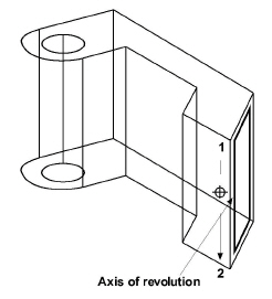
Tech Note: Be aware of the right hand rule of revolution. Click the upper point on the axis first to revolve in the proper direction.
The rectangle revolves.
5. Save or delete the part.
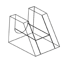
Exercise 7: Projecting an Arc on an Angle in 3D
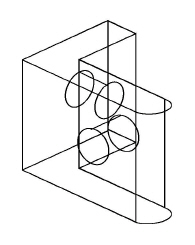
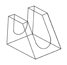
In this exercise, explore 3D drawing further, and construct this model.
1. Open a new document and show the Trimetric view.
2. Use the Connected Lines tool to follow these steps:
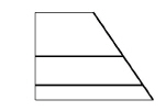
3. Draw the single line representing the width of the part.
Tip: As your need for 3D becomes more serious check out Ashlar-Vellum's products for 3D modeling, including Cobalt, Xenon and Argon.
With all lines selected, except the last one drawn, use the Mirror tool with the Copy option (CTRL key - Windows, OPTION key - Macintosh) to make a mirror copy along the mirror line perpendicular to the midpoint of the width line.
Tech Note: The Mirror tool only works in the x,y plane. In this model, mirroring works correctly, but if the work plane is changed, mirroring may not work.
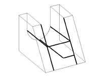
4. Connect the front edges.
5. Use the Connected Lines tool to make the back opening.
Change the work plane to Right to place the arc correctly.
• Continue the construction as shown here:
6. Construct the ellipse on the slanted face.
• Add construction lines as shown in bold below.
Tip: Remember when using tools which require specification of three points, the work plane does not need to be moved.
• Draw another construction line from the midpoint of the arc, as shown.
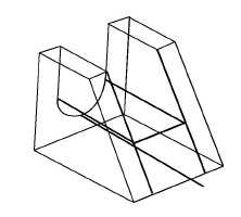
Tech Note: With these construction lines, it is not necessary to specify the center and one point on a 3-point center ellipse. It is still necessary to specify the corner of a box bounding the ellipse.
• From the Front view, trim this line back to the front face.
• Draw a construction line from the endpoint of the last line, perpendicular to the edge of the slanted face.
• Choose the 3-Point Center Ellipse tool. The Message Line reads, 3-Point Center Ellipse: Pick center of ellipse [Ctrl = Copy Previous (Windows) or Option = Copy Previous (Macintosh)].
Tip: Rotate the part with the Trackball to see the intersections clearly.
Specify the points as shown.
The ellipse appears.
7. Delete the construction lines and trim the upper half of the ellipse.
The model is complete.
8. Save or discard the part.
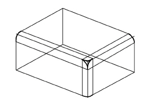
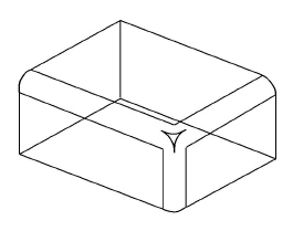
Exercise 8: Three-Corner Fillets
This exercise works with one of the trickiest 3D modeling problems, trimming the corner of a box where three fillets intersect.
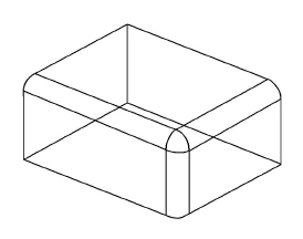
1. Begin by drawing a box.
2. Fillet three corners as shown below.
Tip: With the 2-Entity Fillet tool do not worry about changing the work plane around. The fillet is automatically placed in the plane based on the two selected lines.
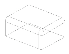
3. Extrude the fillets.
• Select the bottom fillet.
• Choose 3D>Extrude.
• Drag from one end of the line as shown below to indicate the extrusion distance and click OK.
The fillet is extruded.
• Extrude the other fillets.
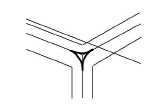
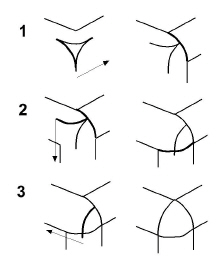
4. Trim the intersecting lines at the corner.
• Use the Corner Trim tool and trim the corner as shown.
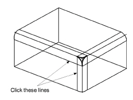
The corner trims.
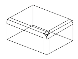
• Trim the remaining corners, as illustrated.
5. Delete the lines which made up the edges of the cube before adding the fillets.
Tip: Create a new layer and move those lines to that layer, then hide that layer to use them again.
6. Move the remaining arcs into the proper positions.
The cube corners are filleted.
7. Check the Top, Right and Front views to see if they look correct.
8. Save or discard the drawing.
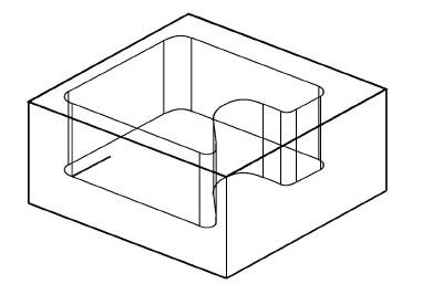
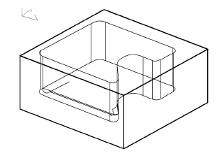
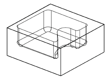
In this exercise, create a fillet at the bottom of a pocket.
1. Begin by drawing a model similar to the one below.
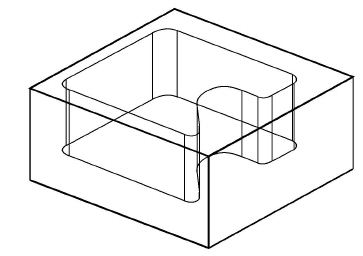
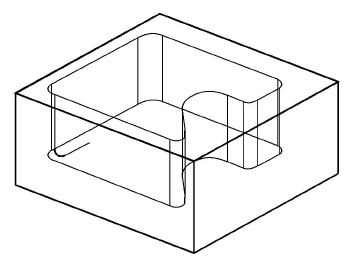
2. Draw a line in the plane of the floor, perpendicular to the pocket side.
3. Construct a fillet between the line on the floor and the line on the side.
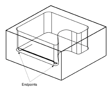
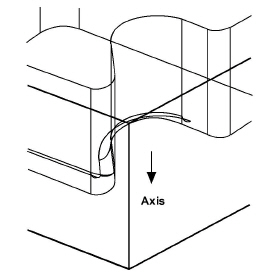
4. Extrude the fillet arc along the length of the side, from endpoint to endpoint.
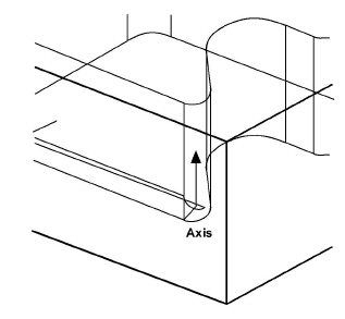
5. Revolve the fillet arc around the corner radius, the number of degrees of the corner angle, using a vector from the corner radius center and 2 steps.
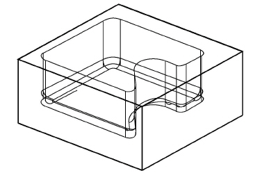
6. Extrude along the next straight line segment.
7. Revolve around the curve, by the degrees of the curve angle, using a vector from the radius center.
Tech Note: Use Edit Objects to find the value of the angle of the curve.
8. Complete the boundary by extruding along the lines and revolving around the arcs.
9. Delete the original boundary and the line added to create the fillet initially.
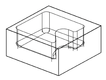
10. Trim the vertical lines to the top of the new boundary.
The model is complete.
11. Look at the other views (Front, Top and Right) of the model.
Tech Note: Remember to hold down the SHIFT (Windows) or the CONTROL (Macintosh) key when zooming in the active view window.
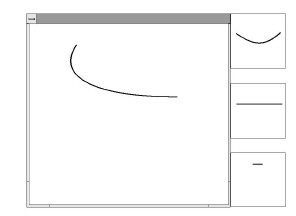
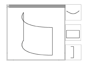
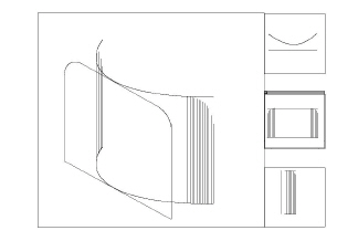
In this exercise, create a compound curve using multiple views.
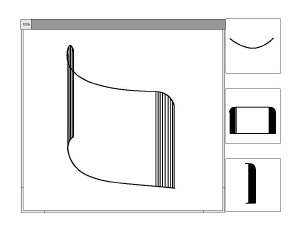
1. Open a new document.
2. Draw an arc so that the endpoints of the arc lie on a horizontal line.
3. Set up design views, to see the work from different view points.
• Choose Views>Sheet Into View.
• Choose A Landscape 4 Views.vc6 from the pop-up menu.
• Click OK.
Zoom to see the arc properly.
The arc displays in the views.
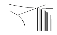
4. Extrude the arc in the z direction.
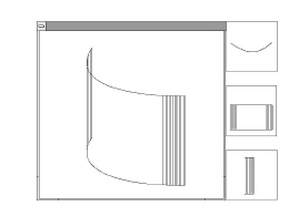
5. Add lines on the surface of the cylinder.
• Select the extrusion line at the left end of the arc.
• Choose Edit>Polar Duplicate.
Specify 8 for the number of duplicates.
Activate the Center X data field with the TAB key. First touch the arc with the bull’s eye cursor to a waken the center point and then click on the center point of the arc.
Make the step angle 2°.
Click OK to finish the operation.
• Repeat the process for the other end of the cylinder, making the step angle –2°.
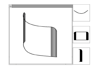
6. Create the profile of the compound curve.
Use the Selection tool + CTRL (Windows) or OPTION (Macintosh) key to make copies of the original extrusion lines in front of the surface aligned on the y axis.
• Select the two original extrusion lines that go between the arcs.
• Move the cursor near an endpoint of one of the lines. Hold down the CTRL (Windows) or OPTION (Macintosh) key and drag a copy of the lines out along the y-axis as shown in the next graphic.
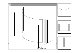
• Connect the top and bottom of the lines with the Single Line tool to make a rectangle.
• Choose 3D>Planes>Front.
• Fillet the corners as shown.
Tech Note: If the drawing looks right in the Top and Front views, then the drawing is right.
• Make sure that the fillets are selected and use them as the boundary of a trim operation. In the Front view, trim off the parts of the surface lines that appear above the fillets.
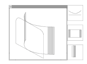
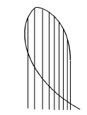
7. Complete the curve.
• Draw a line from the beginning of the fillet to the cylinder.
• Trim the cylinder arc.
• Delete the construction line marking the end of the fillet.
• Repeat the process for the other fillet.
• Delete the profile form.
• Use the Through-Points Spline tool to connect the endpoints of the cylinder at ends of the surface lines.
8. Save or discard the drawing.
These exercises demonstrated many of the techniques for 3D drawing. They showed how to use the Z-Drafting Assistant for isometric drawing and demonstrated the Extrude and Revolve commands.
In addition to those basic construction methods, you learned how to rotate the view orientation and move the work plane. Finally, two of the most complex 3D problems were solved, intersecting multiple fillets and driving a fillet around a boundary.
Combining all these techniques with what you already know using Graphite you can create amazingly complex finished drawings.