


GD&T stands for Geometric Dimensioning and Tolerancing, a U.S. government standard. This GD&T capability is compliant with ANSI Y14.5 (1985), DIN, ISO and JIS standards.
Since this annotation may be new to you, this section includes an overview of GD&T standards and a brief explanation of the components of a GD&T label, using the true position of holes as an example. The topics covered include:
Before World War II, a single vendor did most military manufacturing for a particular part of product. During the war, however, it became a matter of national security to diversify weapons manufacturing so a single plant was not the only source of a vital part. When more than one manufacturer interpreted specifications and blueprints, difficulties arose.
When several companies manufacture the same part, each must drill holes within the same tolerance for the parts to be interchangeable. Even though manufacturers thought they were following the tolerance specifications, the parts were not interchangeable. The problem arose from the order in which measurements were made.
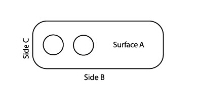
A part was usually laid on a flat surface (A) and aligned first with one straight edge (B), then with another (C).
If one manufacturer aligned with edge B, then edge C, but another aligned with edge C, then edge B, the resulting measurements would probably be different. The GD&T standards tell a manufacturer the order of alignment.
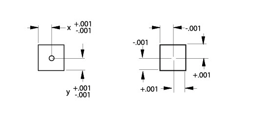
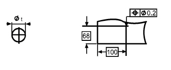
In addition to the alignment information, a manufacturer gets a bonus from GD&T tolerances. In conventional drafting, the tolerance for hole drilling results in a square target area. For example, examine the plate on the left below. The positional tolerance for the hole is ±.001. The target area (magnified and shown on the right) is from .001 left of the perfect center to .001 right of the perfect center, and .001 above the perfect center to .001 below the perfect center.
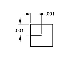
GD&T provides a circular target area for the hole. First measure from the center in one direction by the distance of the tolerance; then measure the same distance perpendicular to that point.
Then use the distance from the endpoint of the second line to the perfect center as the radius of a circle to create a circular target—the bonus tolerance.
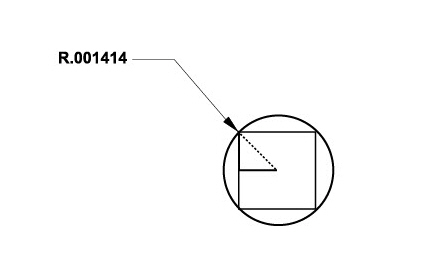
In that way, the target area for the hole’s center is the area circumscribing the square of standard dimensions.
The standard information (basic dimensions) about the target area appears in a box with a GD&T feature control frame.
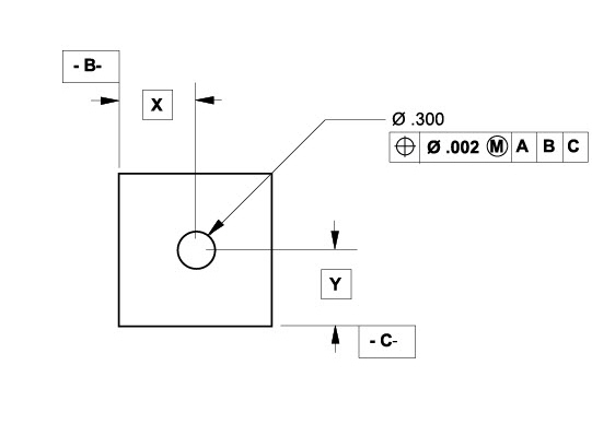
Since the tolerance for a dimension is in the feature control frame, GD&T dimensions are also basic dimensions and appear in a box. The value defines the theoretically perfect location and implies that the tolerance is in the feature control frame.
To specify the basic dimension format, in the Dimension menu, go to the Linear and Angular submenus, and choose [xxx] (basic).
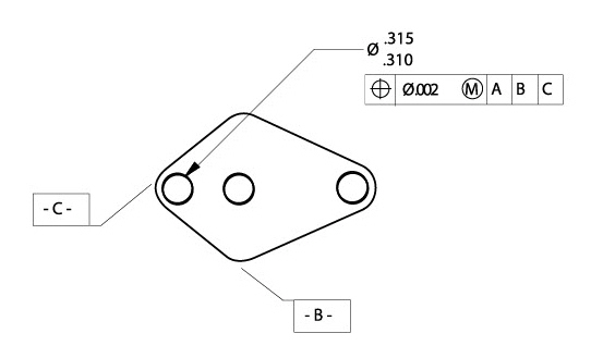
This section discusses the GD&T labeling of the left hole in the plate below.
Typically, the GD&T feature control frame appears as shown below:
The first section of the feature control frame contains the geometric characteristic symbol. The feature control frame on the previous page describes True Position—how to locate the circular target area for the hole. The possible characteristics are as follows:
|
 Straightness
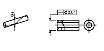
 Flatness
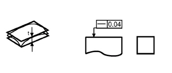
 Roundness
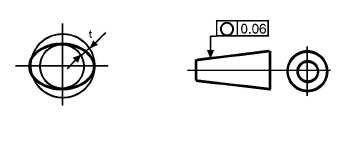
 Cylindricity
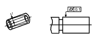
 Profile of Line
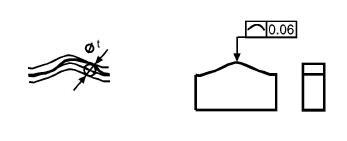
 Angularity
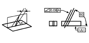
 Perpendicularity
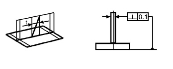
 Parallelism
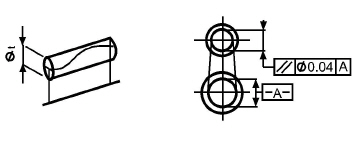

 Concentricity
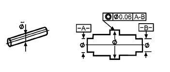
 Symmetry
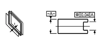
 Circular Runout
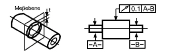
 Total Runout
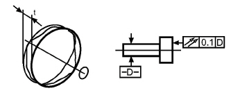
The second section of the feature control frame specifies whether the tolerance applies to a circular zone. If it does, specify the diameter symbol (Ø) from the pop-up menu.
Tip: If the diameter symbol is appropriate for the geometry, it should be displayed. It is usually not used with flatness, roundness, cylindricity, profile of line or surface, angularity, circular or total runout.
The third section of the feature control frame defines the tolerance allowed under the stated conditions.
The fourth section of the feature control frame provides the material condition for limiting the tolerance. Use any of three material conditions: Maximum, Least and Regardless of Feature Size.
Maximum Material Condition (MMC) indicates that a feature contains the maximum amount of material within the specified tolerance limit. For drilling holes, MMC means that the drill bit is accurate—it drills the smallest hole. For shafts, MMC results in the largest dimension.
Tip: Maximum Material Condition is the most commonly used symbol for parts.
In the example above, this material condition symbol means that the tolerance in the feature control frame (.002) applies to the location of the smallest hole (.310 in this case). As the hole size nears its upper limit (.315), the location of the hole increases from .002 to .007 (the tolerance for the location, .002, plus the tolerance for size, .005).
Least Material Condition (LMC) indicates that a feature contains the minimum amount of material within its specified tolerance limit. For holes, the swept area is the largest and the drill bit drills the largest hole. For shafts, the tolerance is the smallest allowable dimension.
In the example above, this material condition symbol means that the tolerance (.002) applies to the location of the largest hole (.315). As the hole size nears its lower limit (.310), the tolerance for the location of the hole increases from .002 to .007 (the tolerance for the location, .002, plus the tolerance for size, .005).
Tip: Least Material Condition is most frequently used to control wall thicknesses of parts, as well as for tool fixtures and inspection gauging.
The Regardless of Feature Size (RFS) material condition means the tolerance applies regardless of the size of the feature (within the specified tolerance limit). For holes, the location tolerance is the same regardless of whether the hole is the smallest or largest allowable size. For shafts, the roundness tolerance is the same regardless of the shaft diameter.
In the example above, this material condition symbol in the feature control frame (.002) applies to the location of the hole whether the hole is at its smallest (.310) or largest (.315). This material condition would control an axis in space, so you probably wouldn’t use Regardless of Feature for this hole.
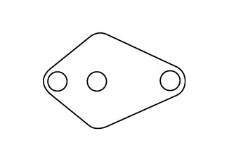
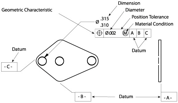
The last three sections of the frame show the alignment order to position the part. This is easier to see in a part which does not have perpendicular sides. A typical engineering drawing might appear as shown below:
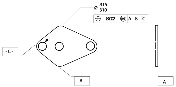
For proper drilling alignment and measurement, this part would lie on a flat surface (Surface A), with Side B pushed against the first straight edge, and then Side C pushed against the other straight edge.
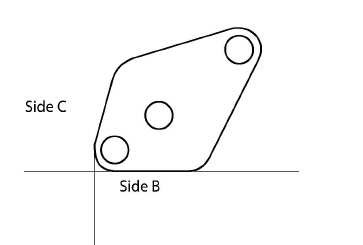
GD&T tells a manufacturer which surface to align first. If the part is aligned with Side C before Side B, the holes do not line up in the same way as they would if Side B was aligned before Side C.
The rule for points of contact per surface is as follows:
|
When showing a datum in a feature control frame, there is also the option of indicating a material condition. Such a modifier should only be specified for a datum that is an axis or centerplane of a feature, such as a hole or boss. Material Condition modifiers do not apply to planes such as the straight side or flat bottom of a part.
A composite symbol uses more than one line of the feature control frame to specify more than one tolerance for the same feature.
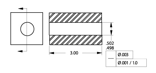
The first line of the feature control frame means that the hole must be straight throughout within a cylindrical tolerance of .003 diameter for the total of its length, 3.00 inches. The second line of the frame means that the hole must be straight for any 1.00 inch portion within a cylindrical tolerance of .001 diameter. Graphite creates the composite frame automatically if the same symbol is in Line 1 and Line 2 of the dialog box.
This entry box of the feature control frame specifies an area above the actual part where the tolerance of a feature should still apply if the feature were extended or projected into the area. For example, if an outboard motor has a hole in the housing, the hole has to be straight not only through the housing, but also down into the propeller assembly, so that the drive shaft aligns properly.
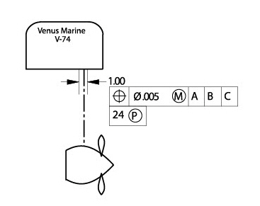
In the motor example, the tolerance for the hole should be checked 24 inches from the actual hole.
The GD&T command in the Dimension menu creates a label, a feature control frame for showing dimensions, alignment, and tolerances. The dialog box looks like a complex GD&T symbol into which the information can be entered.
The GD&T label uses Plotter fonts so the font size corresponds to ANSI standards, since the sizes of other fonts are not always consistent with ANSI standards. If the size of the dimensions needs to be the same as the font in a GD&T label, select the dimensions and change the font size or choose the plotter font.
The GD&T dialog box resembles a GD&T label. For 3D geometry, GD&T labels are created parallel to the work plane.
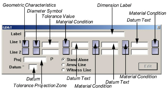
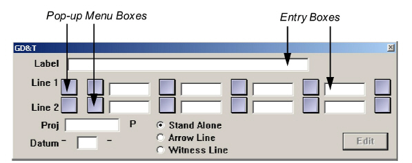
The square boxes are pop-up menus from which symbols are selected. Use a single entry, a line, or a combination of lines as needed to specify the GD&T dimensions for the part.
1. Choose Dimension>GD&T. The GD&T dialog box appears.
2. Click a button (Stand Alone, Arrow Line, or Witness Line) to indicate the way the GD&T symbol is connected to the geometry being labeling.
3. Enter the appropriate data to create the GD&T label. Make two types of entries in this dialog box:
• Select symbols from pop-up menus that appear when pressing the square buttons.
• Enter text in the rectangular fields by clicking to place a text cursor, and then typing the entry.
4. Indicate the location of the label. The Message Line guides each successive step.
• For a Stand Alone label, click the location for the upper-left corner of the GD&T label.
• To connect a label with an Arrow Line or Witness Line, click on the geometry to be labeled, and then click on the drawing area to indicate the position for the upper-left corner of the label.
Once a GD&T label is created, it is possible to make changes.
1. Select the GD&T label to be edited.
2. Choose Dimension>GD&T.
The GD&T dialog box appears, displaying the current GD&T information.
3. Make the changes in the GD&T dialog box.
4. Click Edit.
The GD&T label changes.
Using an Editing Shortcut with GD&T
When editing a GD&T label or creating a second label, every entry in Line 1 or Line 2 can be removed.
1. Press the first field to display the Geometric Characteristic menu.
2. Drag to the X symbol.
All entries in the line disappear.