


Bill of Materials is an important extension to CAD programs for tracking and listing parts all the way through the product design and manufacturing process. In the product manufacturing industry every part produced has some type of distinguishing mark—typically the part number—either stamped, etched, embossed, or silk screened onto the part. The manufacturer also needs to document the design and track the characteristics of each part like material, cost of manufacturing, and outside vendor code during the product development process.
The following topics are covered:
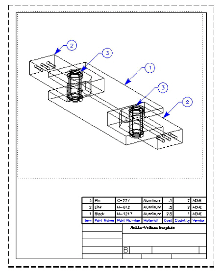
Graphite’s Bill of Materials Extraction utility attaches characteristics (attributes) to the parts being designed. From these attributes, Bill of Materials table is extracted. This Bill of Materials table can be printed separately or with the drawing.
In addition, it is possible to export the Bill of Materials to other applications.
The Bill of Materials Extraction utility is completely integrated in Graphite and combines powerful functionality with an easy to use interface.
Generating a Bill of Materials is a two step process:
• Defining and assigning attributes to object geometry in drawings.
• Extracting user-defined and predefined attributes in the form of lists or ASCII-files for export purposes.
When using the Bill of Materials Extraction utility for the first time, start by interviewing all the groups within your organization to determine which characteristics need to be tracked. The next step is to assign these characteristics to an existing catalog of parts, typically Graphite symbol files. These parts can then be used to create an assembly or installation drawing. These attributes can then be extracted into a Bill of Materials table or exported for use in other applications.
The Bill of Material distinguishes between two kinds of attributes:
|
Non-numerical attributes like line color and line style are not recognized by the Bill of Materials.
Each object created in Graphite automatically has different kinds of attributes: numerical attributes like the perimeter and the area of a circle, and non-numerical attributes like the line color and the line style.
With the Bill of Materials Extraction utility, assign User-defined Attributes to objects, like a Part Name or Part Number.
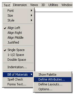
Before assigning attributes to objects, they must first be defined. To define attributes choose Text>Bill of Materials>Define Attributes.
This command defines, deletes, redefines and activates attributes. Active attributes (attributes which can be assigned) are indicated by an eye icon in front of the attribute name. Locked attributes (their values cannot be changed during assignment) are indicated by a lock icon in front of the check mark.
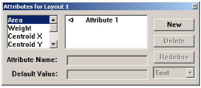
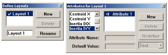
The Define Attributes command displays the dialog box on the right.
Attributes are defined in the Define Attributes dialog box by three parameters:
|
The Define Attributes dialog box contains the following buttons:
|
1. Click New to create a new attribute.
In the Attribute Name entry field Attribute 1 displays.
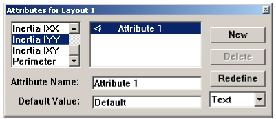
2. Rename the attribute by typing a name in the Attribute Name entry field, like COST.
3. Specify a value for the attribute in the Default Value entry field.
The value can be changed in the Status Line during assignment, like 2.50. The format must be Text, not Number if the $sign is used.
4. Select a format for the new attribute. In the examples given above, the format is Number.
Click the Format pop-up menu and select.

5. Click Redefine.
The new attribute name appears in the attributes list, and the specified value and format is assigned to the attribute.
6. Close the Define Attributes dialog box.
Only visible attributes (indicated by an eye icon beside the attribute name) are displayed during assignment. Hidden attributes cannot be edited.
1. Select an attribute to show or hide from the list box. The eye icon beside the attribute name indicates that an attribute is visible.
Locking and Unlocking Attributes
To lock or unlock an attribute simply click in front of the attribute's name. The lock icon in front of the name appears or disappears.
The values of locked attributes cannot be changed during assignment.
Changing the Characteristics of an Attribute
Choose the Text>Bill of Materials>Define Attributes to open the Define Attributes dialog box.
1. Select the attribute whose name, value or format needs to be changed.
2. Type a new name or value, or choose a new attribute format.
3. Click Redefine.
The new attribute name appears in the attributes list and the new value and format are assigned to the attribute.
4. Close the Define Attributes dialog box by clicking Close.
Choose Text>Bill of Materials>Define Attributes to open the Define Attributes dialog box.
1. Select the name of the attribute from the list box.
2. Click Delete. The selected attribute deletes.
With the Redefine button, rename an attribute or assign a new value or format to the attribute.
To save all attribute definitions permanently, choose Layout>Preferences>Save Preferences. Close Graphite and relaunch it for the new preferences to take affect.
Predefined Attributes (Graphite Attributes)
Predefined Attributes are attributes that Graphite defines. These attributes are calculated and displayed using 2D Analysis (see Chapter 18). Choose the ones from the list by double clicking.
• Centroid Y
• Inertia IXX
• Inertia IYY
• Inertia IXY
For predefined attributes enter the attribute's name only, since their values and formats are predefined. These attributes are displayed in the Status Line but cannot be changed, since Graphite calculates the values automatically.
Assign attributes using the BOM tools. Activate BOM tools like any other tool in the Graphite tool palette.
An object's attributes are inaccessible if the object is grouped, so that the group itself can have attributes. The object's attributes are made accessible by ungrouping the group. Ungrouping a group with attributes removes the group's attributes.
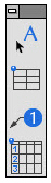
Graphite’s BOM tools are on a separate palette which can be dragged around the drawing area. The palette displays by choosing Text>Bill of Materials>Show Palette.
Choose Text>Bill of Materials>Show Palette or Hide Palette, to display or hide the BOM palette.
Remove the tool palette using the button at the top of the palette.
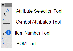

With the attribute tools, assign attributes to object geometry or mark an object as a symbol. By selecting one of these tools all attributes of the current BOM layout display in the Status Line. Hidden attributes do not display in the Status Line.

The attribute values shown in the Status Line can be entered or modified if they are not locked. If they are locked, the attribute’s value is grayed out.

Assign attributes of the current layout to a selected object with this tool.
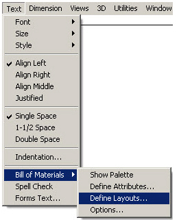
1. Choose Text>Bill of Materials>Define Layouts.
The Define Layouts dialog box displays.
For more information about the Define Layouts dialog box, see the “Bill of Materials Layouts” section later in this chapter.
2. Select a BOM Layout.
3. Close the Define Layouts dialog box by clicking Close.
4. Select Text>Bill of Materials>Define Attributes.
The Define Attribute dialog box displays.
5. Hide all attributes which needn't be assigned to object geometry in the current drawing by deselecting the eye icon next to that attribute.
6. Close the Define Attributes dialog box.
7. In the BOM tool palette, select the Attribute Selection tool. The Message Line reads, User Attribute Tool: Select Geometry...[Return = Append Attribute, Ctrl+Return = Remove Attribute {Windows} or Option+Return = Remove Attribute {Macintosh}].
8. Select the object to which attributes will be assigned.
9. Enter the desired values in the entry field in the Status Line.
Locked attribute values cannot be edited in the Status Line.
10. Press the ENTER (Windows) or RETURN (Macintosh) key.
Important: The attributes are assigned only after pressing ENTER (Windows) or RETURN (Macintosh).
Tip: To assign attributes to an object made up of several individual objects, like a rectangle, made up of four single lines, group the object before assigning attributes. Otherwise, the attributes will be assigned to each individual object selected.

This tool marks a symbol with assigned attributes.
Graphite doesn't recognize any difference between drawings and symbols. They are only opened by different commands:
• Drawings are opened by choosing File>Open.
• Symbols are inserted by choosing File>Symbol>Insert.
Symbol attribute tables cannot be edited. They must be deleted and reinserted.
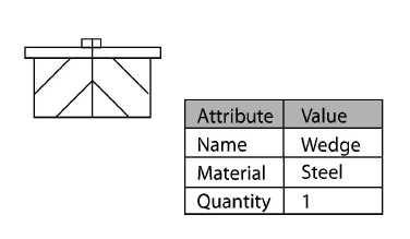
With the Symbol Attributes tool, mark an object with a small table containing all assigned attributes. This table is interpreted when the object is placed as a symbol.
When this object is inserted with the Symbol command all attributes contained in this table are listed in the Symbol dialog box. Values of unlocked attributes can be edited before the symbol is placed—without the attributes table—in the drawing area.
Symbol Attributes do not attach to the objects in the symbol file like object attributes. Instead, Symbol Attributes attach to the symbol when the symbol is inserted into a drawing.
When opening a marked symbol by choosing File>Open the attributes table appears in the drawing area with the symbol.
1. In the BOM tool palette, choose the Symbol Attributes tool. The Message Line reads, BOM Symbol Attribute Tool: Select Insertion Point.

2. Enter the values for the attributes in the Status Line.
3. Click to place the Symbol Attributes table in an empty spot in the drawing area.
A table with all assigned attributes appears with the values entered in the Status Line.
4. Save the object with the Symbol Attributes table.
The attributes in this table attach to the symbol when it is placed using the Symbol command, and the assigned values can be changed in the Symbol dialog box. There should be only one symbol table per file.
If a symbol holding object attributes are placed in the drawing, but no Symbol Attributes table is included, the object attributes do not display in the Symbol dialog box and do not get attached to the symbol when it is placed in the new drawing. To access the object attributes, the symbol must first be ungrouped.
An object can have both object attributes and symbol attributes, and their values do not have to be the same.
Assigned attributes display in the Status Line, where the default values are edited.
1. In the BOM tool palette, select the Attribute Selection tool.

2. Move the mouse pointer over the drawing area. As soon as the pointer comes near an object with assigned attributes, these attributes and their respective values automatically display in the Status Line.
Important: Attributes must be visible (eye icon displaying) and the proper layout must be active, as indicated in the Define Attributes dialog box and in the Define Layouts dialog box in order to display assigned attributes in the Status Line.
Changing the Values of Attributes
1. In the BOM tool palette, select the Attribute Selection tool.

2. Move the mouse pointer near an object with assigned attributes.
The attributes and their respective values display in the Status Line.
3. Select the object with the Attribute Selection tool.
4. Change the respective values in the Status Line. To remove an attribute value, delete the value in the entry field.
5. Press the ENTER (Windows) or RETURN (Macintosh) key.
The changed values are assigned to the selected attribute.
Tip: Values of attributes can also be edited in the Edit Objects dialog box. To do so, select the object, choose Edit>Edit Objects change the value in the Edit Objects dialog box and click Apply.
1. In the BOM tool palette select the Attribute Selection tool.

2. Move the mouse pointer near an object with assigned attributes.
The attributes and their respective values display in the Status Line.
3. Select the object with the Attribute Selection tool.
4. Press the CTRL+ENTER keys (Windows) or the OPTION+RETURN key (Macintosh) simultaneously. All visible and unlocked attributes are removed.
The BOM tool palette assigns item numbers to objects which will be automatically included in the Bill of Materials table.
Item numbers are assigned with the Item Number tool in the BOM tool palette.
Do not use Graphite's Balloon tool from Graphite's Dimension palette to assign Item Numbers for objects to be listed in the Bill of Materials. Item Numbers created with the Balloon tool are not recognized by Graphite's Bill of Materials Extraction utility.

With this tool in the BOM tool palette, assign Item Numbers to objects. These Item Numbers will automatically be included in the Bill of Materials.
1. In the BOM tool palette, select the Item Number tool. The Message Line reads, Item Number Tool: Pick BOM geometry to point to... [Ctrl = Renumber].
2. Three entry fields display in the Status Line: Item, Width and Size.
3. Enter the starting item number for the selected object into the Item field.
Item Numbers can also contain alpha characters—A, B, C, etc.
4. Click the Item Number tool near the object to be labeled.
5. Click with the Item Number tool in the drawing area to indicate the position of the Item Number balloon.
The Item Numbers are placed at the clicked location.
When placing additional position balloons the Item Number automatically increases. The default Item Number always increments from the last Item Number used.
If an Item Number is assigned to an object already assigned to another object, the item numbers adjust as follows:
• If the new Item Number is lower than the highest Item Number already assigned, all higher Item Numbers increase.
• If the new Item Number is higher than the highest assigned Item Number, the existing Item Numbers remain unchanged.
More than one Item Number cannot be assigned to an object. If so, the original Item Number balloon deletes. To get the original Item Number back, do an Undo.
Adjusting Item Number Balloon and Text Size
The following procedure describes how to adjust the Item Number balloon and Text size before assigning any Item Numbers.
1. In the BOM tool palette, select the Item Number tool.

The entry fields, Item, Width and Size, display in the Status Line.
2. Press the TAB key twice and enter the desired width for the Item Number balloon. The units for the indicated width are based on the unit specified in the Units dialog box from the Layout>Preferences>Units.
3. Enter the desired size.
4. Select the desired text size.
The text size of the Item Number balloon is now set.
5. Press the ENTER (Windows) or RETURN (Macintosh) key.
The size of the Item Number balloon is now set.
Tip: An Item Number’s font is specified in the Font submenu of the Dimension menu.
Item Number, Text Size and the Size of the Item Number balloon can be changed.
Editing the Size of an Existing Item Number Balloon
1. Select the desired Item Number balloon.
2. Choose Item Number Tool.
3. In the Status Line, enter the new diameter in the width field.
4. Press the ENTER (Windows) or RETURN (Macintosh) key.
The diameter of the selected Item Number balloon updates accordingly.
1. Select the respective Item Number balloon.
2. Choose Edit>Edit Objects.
3. In the Status Line, enter the new Text Size in the size field.
4. Press the ENTER (Windows) or RETURN (Macintosh) key.
The text size of the selected Item Number balloon update accordingly.
Item Number text size can be changed dynamically by selecting the Item Number balloon and changing the size in the Dimension menu.
Tip: The shape of the Item Number balloon can also be changed in Edit Objects. If existing Item Numbers are renumbered, all Item Number balloons revert to the default circle balloon.
1. Select the desired Item Number balloon.
2. Select Edit>Delete or press the BACKSPACE (Windows) or DELETE (Macintosh) key.
The selected Item Number will be deleted.
Renumbering Existing Item Numbers
1. In the BOM tool palette, select the Item Number tool.

The entry fields, Item, Width and Size, display in the Status Line.
2. Enter in the Item field the new starting number for the Item Number, press the ENTER (Windows) or RETURN (Macintosh) key.
3. Press the CTRL (Windows) or OPTION (Macintosh) key and keep it pressed.
4. Click the Item Number balloons in the desired order.
The Item Number balloon will split. The upper half of the symbol shows the old Item Number and the lower half of the symbol the new Item Number.
5. Release the CTRL (Windows) or OPTION (Macintosh) key.
All Item Numbers renumber.
Item Numbers and Object Copies
The Item Number tool automatically recognizes if an object is a copy of an object to which an Item Number is already assigned, as long as the original object has an attribute of the Quantity. The Item Number tool automatically assigns the identical Item Number of the original object to the object copy.
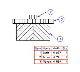
After assigning attributes to objects, create a Bill of Materials. The Bill of Materials will contain all Item Numbers and their associated attributes.
|
The Bill of Materials is placed on the current sheet. Move it to another location, copy it to another sheet or export it into an ASCII file to use it in other programs like spread sheets or text editors.
In order to create a Bill of Materials, first define a layout.
The Layouts command defines different layouts for the Bill of Materials and is used in conjunction with the Define Attributes dialog box. To define layouts, choose Text>Bill of Materials>Define Layouts.
The Layouts command, in the BOM submenu of the Text menu, displays the following dialog box:
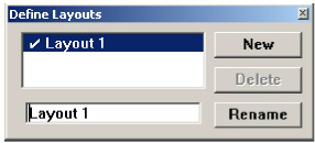
Layouts differ only by the attributes to which they relate. A layout contains all the visible attributes listed in the Define Attributes dialog box. (Visible attributes are indicated by a check mark.) Therefore, the Define Attributes dialog box should be displayed when defining a layout.
1. Choose Text>Bill of Materials>Define Layouts.
The Define Layouts dialog box appears.
2. Click New.
3. Rename the layout in the Layout Name entry field.
4. Click Rename.
5. Double click to activate/set.
6. Select the Text>Bill of Materials>Define Attributes.
The Define Attributes dialog box displays.
7. Define all the attributes to be used in different layouts.
8. Make all the attributes visible to be saved under one layout name.
All active attributes in the Define Attribute dialog box are automatically saved under the current layout name for the current Graphite session.To save layouts permanently, choose Layout>Preferences>Save Preferences.
1. Choose Text>Bill of Materials>Define Layouts.
The Define Layout dialog box displays.
2. Double click to activate/select.
3. Click Current.
4. Select the Text>Bill of Materials>Define Attributes.
The Define Attribute dialog box displays.
5. Show or Hide the attributes as desired.
All changes made in the Define Attribute dialog box are automatically saved under the current layout name. To save the changes permanently, choose Layout> Preferences>Save Preferences.
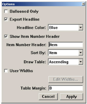
For all BOM layouts defined, some of the preferences can be set globally.
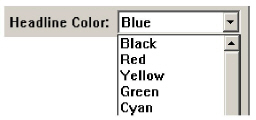
Select the Text>Bill of Materials>Options and this dialog box displays.
|
Specifies the width of the BOM columns individually.
The Edit button activates. Clicking Edit displays the following dialog box:
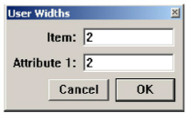
In this dialog box all attributes of the actual layout appear. For each attribute the respective column width displays. The displayed values for the column widths are calculated by the word length of each attribute and the indicated margin. Change the width for each column individually. All specified values are based on the units set in the Units dialog box (Layout>Preferences>Units).
The order by which the attributes displays in the Bill of Materials is determined by the order the attributes were defined in the Define Attribute dialog box and cannot be changed in this box.
A Bill of Materials contains all the Item Numbers and their associated attributes. The generated Bill of Materials is an object in Graphite like any other object geometry. That means it can be moved, copied, deleted and edited. Create a Bill of Materials with the Bill of Materials tool in the BOM tool palette.
Tip: Macintosh users: drag the attribute names in the Attribute List in the Define Attributes dialog box to change the order.

This tool, in the BOM tool palette, generates a Bill of Materials of the current model and places it on the current sheet. Its insertion point is based on the Draw Table setting in the Options dialog box.
Creating a Bill of Materials for the Entire Drawing
1. Choose Text>Bill of Materials>Show Palette.
The BOM palette displays.
2. Select the BOM tool. The Message Line reads, BOM Tool: Pick Insertion Point [Ctrl = Selection Only {Windows}, OPTION = Selection Only {Macintosh}].
3. Click in the drawing area to indicate the location to display the Bill of Materials.
The Bill of Materials of the current layout appears at the selected location. The Bill of Materials uses the font currently selected in the Text menu. It can be moved, copied or deleted like any other object in Graphite.
Creating a Bill of Materials of Selected Objects
1. Select all objects to display in a Bill of Materials.
2. Choose Text>Bill of Materials>Show Palette.
The BOM palette displays.
3. Select the BOM tool.

4. With the CTRL (Windows) or OPTION (Macintosh) key pressed, click in the drawing area to indicate where to place the Bill of Materials.
A Bill of Materials containing the selected objects is created and placed at the location indicated with the last mouse click.
1. Select the Bill of Materials with the Selection tool.
2. Choose Arrange>Ungroup.
The Bill of Materials ungroups into text and line objects that can be edited.
Attributes assigned to objects in a drawing can be exported into an ASCII file for use in other programs like text editors or spread sheets.
To export a Bill of Materials, select the File>Export. The displayed Export dialog box contains the export option Bill of Materials.
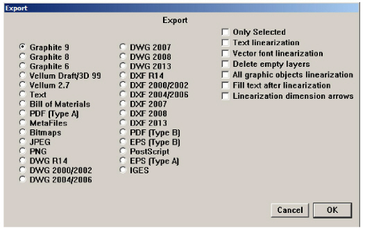
1. Select File>Export.
The Export dialog box displays.
2. Mark the Bill of Materials option.
3. Select the Only Selected option to export attributes only from selected objects and not from the entire drawing.
4. Click OK and provide a file name and location.
The Item Numbers and attributes of the entire drawing or of the selected objects only export into an ASCII file.