


The 2D Analysis provides sectional properties for the selected geometry, a feature that is useful for many calculations related to design and drafting. Architects use the perimeter and area values for calculating material requirements; engineers use the moments of inertia for stress analysis; manufacturers use the centroid for balancing parts for turning. The following topics are covered in this section:
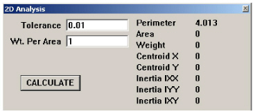
The 2D Analysis command in the Layout menu displays the statistics on the selection, including the length of the perimeter, the enclosed area, the center of gravity (centroid), and moments of inertia. The selection must be a closed figure.
Tech Note: The closed figure is an area that could be crosshatched. If in doubt about the area, simply crosshatch the geometry to see if it represents the area that needs to be analyzed.
1. Select the geometry that defines a closed boundary. Use the Tracer tool to select the perimeter.
2. Choose Layout>2D Analysis.
The analysis is performed and the values appear in the dialog box.
3. If necessary, enter changes for the tolerance and weight per area values.
Tech Note: Once the area is crosshatched and the selection is correct, choose Undo to remove the crosshatching and still maintain the selection.
4. Click CALCULATE.
The analysis recalculates and the new values appear in the dialog box.
The following items are included in the dialog box:
Tech Note: This tolerance value has no effect on the precision of the resultant values. The precision of the result is set by choosing Layout>Preferences>Units.
|
Graphite calculates the values for 2D Analysis before the dialog box appears. To make a change in the Tolerance or the Weight Per Area, click CALCULATE to recalculate the statistics.
The 2D Analysis mechanism evaluates the boundary in the same way the crosshatching mechanism does. For example, Graphite considers a circle inside a bounded area to be a hole. Crosshatching does not fill the hole and 2D Analysis does not include the area of the circle in the area calculation.
1. Select the geometry defining the part.
2. Choose Layout>2D Analysis.
The 2D Analysis dialog box appears.
3. Choose Layout>Construction.
The Construction dialog box appears.
4. In the Angle field in the Construction dialog box, enter 0;90. (Be certain to separate the numbers with a semicolon.)
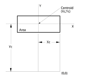
5. Enter the value for Centroid X in the X field of the Construction dialog box.
6. Enter the value for Centroid Y in the Y field of the Construction dialog box.
7. Press ENTER (Windows) or RETURN (Macintosh).
Construction lines display, intersecting at the centroid of the selected part.