


In Graphite it is possible to place any drawing as a symbol and open any symbol as a drawing. Create symbol documents for generic, parameterized parts, and then bring them into the drawing, customizing the dimensions with each use. Symbols are particularly useful for creating a library of standard designs common to your work. For example, create libraries of windows, screws, nuts or bolts.
Graphite distinguishes between:
• Simple symbols, which have neither parametric dimensions nor underlying value tables
• Parametric symbols, with editable dimensions
• Symbol libraries, that contain parametric symbols with underlying value tables.
All commands used to manipulate symbols are found by choosing File>Symbols....
Most of the symbols shipped with Graphite are parametric symbols. Parametric means that the symbol's final measurements can be specified just before placing them into a drawing. This feature uses one symbol in countless variations.
The following topics are covered in this chapter:
The installation procedure copied the parameterized symbols in to the Symbols folder of the Graphite folder. Look at some of those symbols to get an idea of the type of symbols to be created with Graphite.
When a symbol is brought into a drawing, it is necessary to indicate its location and orientation. In order for this to work properly, a control point must be at the Origin (0,0) in the original symbol file.
As a special feature for use with parametrics, lines in the Construction pen style do not appear with the symbol when it comes into a document. Use this feature to define your own smart windows and smart doors, as well as other symbols.
1. Construct the geometry, using the Construction pen style for any lines that should not appear in the symbol when it comes into a drawing. Be sure to place one control point at (0,0) to specify the location of the symbol when bringing it into a drawing.
2. Dimension all aspects of the part by entering a variable in the text data field in the status line of each dimension.
3. Choose Edit>Resolve to check the accuracy of the parametric dimensions.
4. Choose File>Save As.
5. Name the document.
It is a very easy process to place symbols into the drawing. Using File>Symbol..., place either newly created symbols or those that came with the program.
When selecting Symbol in the File menu, an open file dialog box appears. Use the dialog box to navigate and select a symbol directory. All the symbols in that directory are loaded into the Symbol Panel and their file names display along the left side of the Symbol Panel.
Choose File>Symbol... and a standard open file dialog box displays. Once a symbol is selected, the Symbol Panel appears.
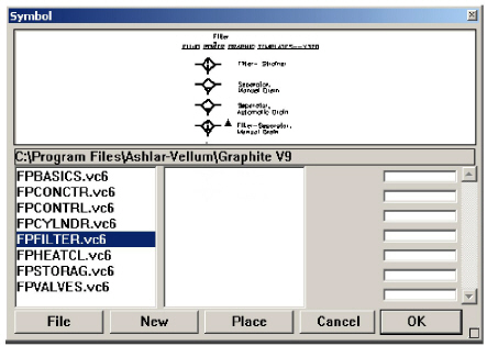
The dialog box displays a preview of the symbol and lists the file names of all other symbols stored in that directory. The Symbol Panel is resizeable.
For parametric symbols, entry fields for all variables defining the symbol are displayed.
To place the symbol in the drawing, click or drag a vector on the drawing area. Click and the symbol inserts at the clicked location, in its original orientation. Drag and the starting point of the drag specifies the insertion point for the symbol and the direction of the drag indicates the orientation.
Tech Note: Click the small resize box in the lower right corner of the Symbol Panel to drag and resize the symbol. Shift click to minimize the panel (for use on nonparametric symbols, such as nuts, bolts, valves, etc.)
Bringing a Symbol into the Current Document
1. Choose File>Symbol....
The Open dialog box appears.
2. Select the symbol file to be used and click Open.
The Symbol dialog box appears displaying a preview of the currently selected symbol. All symbol files in that directory appear in the symbols list on the left side of the Symbol Panel.
3. Enter a value for each of the parametric dimensions.
4. Specify the location and orientation for the symbol.
In the dialog box, a triangle appears on the geometry to indicate the origin or the point being located. Click, the symbol inserts at the clicked location, in its original orientation.
Drag and the starting point of the drag specifies the insertion point for the symbol and the direction of the drag indicates the orientation.
If a location is not specified, scroll as necessary to see the symbol.
5. Click OK.
The geometry resolves and appears in the current drawing at the location clicked, sized as specified.
The symbol geometry is selected so it can be moved to a new location.
6. Add regular dimensions if desired.
To see an enlargement of any part of the symbol within the viewing window, move the pointer to the area of interest and press the mouse button. The enlargement reduces when the mouse button is released.
Tech Note: Use a text file to fill in parametric dimensions of a symbol. Create a text file with value pairings for each variable and its value. Then load the symbol and click on File in the Symbol Panel. The file automatically fills in the values specified for each dimension.
Browsing a Directory of Symbols
1. Choose File>Symbol....
The Open dialog box appears.
2. Select a symbol file from the directory to be browsed and click Open.
The Symbol dialog box appears displaying a preview of the currently selected symbol. All symbol files in that directory appear in the symbols list on the left side of the Symbol Panel. (To change the selected symbol, click on a file name from the list along the left side of the Symbol Panel. The preview pane updates to display the currently selected symbol.)
3. Click New to load a different directory of symbols.
Use the Import command from the File menu to bring in the geometry and dimensions of a symbol. When importing a symbol, it comes into the current drawing at the size it was drawn. Specify new measurements by choosing Edit>Edit Objects or choose Edit>Select All and then choose Edit>Resolve to change the size.
Using the Edit Objects command it is possible to edit parametric symbols placed in a drawing. After selecting the symbol, choose Edit>Edit Objects, then edit the dimension of the symbol.
The Architect folder of the Symbols folder contains smart symbols for doors and windows. Smart window and door symbols are smart because they contain a smart wall segment. Adding one of these symbols to a smart wall breaks it into the wall in the specified location.
When creating custom smart symbols, draw smart walls with the Construction pen style. (Geometry created with the Construction pen does not appear when it is brought into a drawing.) The invisible geometry is still functional in that existing smart walls in the drawing detect the invisible wall of the symbol.
Draw a thick wall in line with or overlapping a thinner wall, so it hides the thinner wall. Therefore, to get a symbol to mask part of a wall, include a single wall that overlays the target wall. To see an example, open one of the smart symbols in the Architect folder that was installed with Graphite.
1. Choose Pen>Style>Construction.
2. Draw a smart wall thicker than the maximum thickness expected to be used and only as long as the final symbol is.
3. Change pen styles to any style other than Construction.
4. Draw the symbol.
5. Choose File>Save As and save as usual.
Using Symbols for Smart Windows and Doors
The Symbols/Architect folder that was installed with Graphite contains symbols for smart windows and smart doors. These symbols work like regular Graphite symbols in that they are parameterized and can be placed and oriented on a drawing. In addition, they break into any smart wall they touch and the cut area of the smart wall fills in if the smart symbols are moved or deleted.