Graphite’s integrated parametrics feature creates geometry without regard to its actual measurements. When the geometry is resolved parametrically, values are specified for the dimensions and Graphite redraws the geometry to the specifications provided. One example of parts that are well-suited to parametric definition are containers that vary in size according to the needs of a product line. Another might be hydraulic pistons that vary in size because of the duty loads. Still another might be valves that vary according to the diameter of the pipes to which they are attached.
This parametric feature is the basis for creating symbols to be used in drafting on a regular basis. See the next chapter for more detailed information.
The following topics cover the parametrics feature:
• Introduction to Parametrics
• Using Parametrics
• Parametric Drafting
• Parametric Problems
• Complex Parametric Drafting
• Parametrics and Grouped Objects
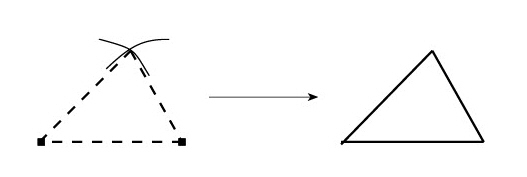
In its simplest form, parametrics allow the creation of a shape and then the specification the exact measurements. Take, for example, the basic activity of constructing triangles using parametric geometry.
1. Create the geometry.
2. Dimension the geometry using variables, constant values, and expressions. As many as 253 parametric dimensions can be used.
3. Resolve the parametric geometry.
Using this method, it is possible to quickly draw a triangle to exact specifications.
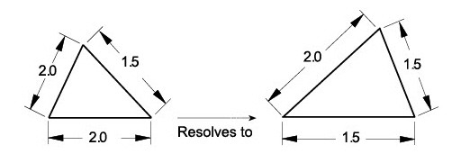
Of course, parametrics can be much more complex when using variables, as seen later in this chapter. While creating geometry is straightforward, when a part becomes complex, parametric dimensioning requires some skill and comprehension of how Graphite treats geometry.
The parametric mechanism is point-driven. It locates the points and then connects them with the appropriate geometry, much like the childhood activity of connect-the-dots. It is not unlike drawing with a compass, triangle, and T-square.
To begin, determine where the endpoints are and then draw lines to connect the points. Or figure out where the center of an arc should be, where the arc begins and ends, and use a compass to connect the points.
Tip: The Graphite folder contains a folder of symbols that use parametrics. You might retrieve a few of the symbols by going to the File menu to the Symbols submenu and choosing the Insert command to become familiar with how parametrics works. See the next chapter for more information on symbols.
1. Define the geometry completely.
Each object must relate to another object.
Dimensions must define every aspect of the geometry. (The geometry may be over dimensioned according to standard drafting practice.)
Do not include extraneous text as part of a dimension. (A single # is acceptable. The parametric mechanism recognizes R # to mean a radius, measuring the real value of the geometry.)
2. Keep it simple. If the part is complex, construct small segments, resolving as you go, solving any parametric problem before proceeding.
3. Return to the original part between tests. Use the Undo command to revert to the original state of the parametric part between tests. In this way, an unwanted constraint won’t be introduced.
4. Consider the following assumptions made by the parametric mechanism:
• Horizontal and vertical lines maintain their orientation.
• Connected lines remain connected.
• Lines tangent to arcs remain tangent (if there is an endpoint at the tangency point).
• Colinear lines remain colinear if they overlap or share endpoints.
• Concentric arcs remain concentric.
• A point of an object on a horizontal or vertical line will remain on that line.
5. Be aware of the relationships that the parametric mechanism cannot recognize:
• Parallel lines may not remain parallel.
• Perpendicular lines may not remain perpendicular.
• Symmetrical geometry may not remain symmetrical.
When approaching the problem of resolving geometry, evaluate it as if drawing it on paper. Remember the assumptions and requirements for geometric relationships as outlined in the previous Basic Rules section.
The essence of parametrics is in the dimensions. The dimensions may be the actual value (gotten by default), a constant which is not the actual value, a single variable, or an algebraic expression involving constants, variables, mathematical operators, functions, and conditional operators.
Constants are specific numeric values, such as specifying a radius as .25 (inch). Variable expressions may be as simple as a single letter such as L (for length), or a mathematical expression such as 2 * Dia (where Dia may be the diameter). The arithmetic operators are addition (+), subtraction (-), multiplication (*), division (/), mod (the remainder after division—%), and exponentiation (**). See Appendix A for a list of functions and conditional operators.
In whatever way the dimensions are specified, they must define all geometry and any relationships that exist between different parts of the geometry.
Creating Parametric Dimensions
1. Construct the geometry.
2. Display the dimension palette and choose the appropriate dimensioning tool.
The Status Line displays a # symbol in the text data field to show that the dimensions are entered as actual measurements.
3. Click the geometry to dimension as usual.
The Text data field in the Status Line highlights.
4. Type whatever expression, variable, or constant to be used for the dimension, and press the ENTER (Windows) or the RETURN (Macintosh) key. To use the actual value, do not overwrite the # symbol in the text data field.
Variables are case sensitive: D is not the same as d.
The expression typed replaces the # symbol.
Examples of Parametric Dimensions and Conditional Expressions
Use the conditional operators as parametric dimensions. Create the dimension as usual and enter the conditional expression as text in the Status Line.
The example here shows a conditional ifelse expression.
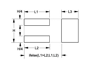
When the above ifelse statement resolves, the rectangle with the larger value (L1 or L2) touches the L3 rectangle.
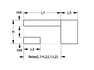
The length represented by the ifelse expression equals L1 because L1 is greater than L2.
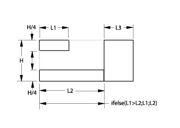
The length represented by the ifelse expression equals L2 because L2 is not less than L1.
Once the geometry is constructed and parametric dimensions are added, use the Resolve command to specify the values for the variables and redraw the geometry.
The Resolve command in the Edit menu redraws geometry automatically to fit specified dimensions. This parametric feature draws a geometric shape without regard to measurements and then Graphite redraws the same shape to the values specified.
Tech Note: Example: Use a mathematical expression with a fastener symbol. For a numbered fastener (#2, #4, #6, etc.,) use the following formula for the thread size: (N*13+60)/1000 where N is fastener number. For a #6 screw, the thread size equals
6*13+60/1000 or .138
Using the Resolve Command with Parametrics
1. Create the geometry.
2. Dimension all geometry by using variables, constant values and expressions. (Dimension the essential, related geometry so Graphite can reconstruct the geometry. Graphite cannot identify parallel or colinear lines.)
• Select the appropriate dimensioning tool.
• Click the geometry to be dimensioned.
• Enter an expression (such as 1.5, x, x+3*y) in the text data field in the Status Line.
• Press the ENTER (Windows) or the RETURN (Macintosh) key.
3. Select the geometry and dimensions to be resolved.
4. Choose Edit>Resolve.
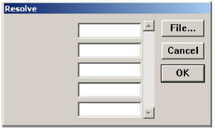
5. If necessary, enter the values to assign to the variables.
Enter mathematical expressions, fractions, and decimals in the data fields of the Resolve dialog box. A mix of different units may be used as long as they are specific, for example 2’6”.
6. Optional step: to anchor a point on the geometry at a particular location, click the point. The point remains in the same location after resolving the geometry. An example appears later in this section.
7. Click OK.
If the parametric dimensions defined the geometry properly, the geometry redraws as specified. The dimensions remain as variable expressions.
If Graphite cannot resolve the parametrics, a message box displays information about the problem. The “Parametric Problems” section, later in this chapter, describes typical problems that may be encountered. If all of the dimensions required to draw the geometry are not provided, the geometry divides into unrelated groups. The missing information determines how the groups relate to one another.
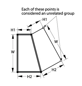
An alert box shows how many groups exist. To see each group, click Next. Examine the groups shown to determine why the position of each group is not related to any other. A group consisting of a single point is particularly telling. (This investigation can require some clever thought because the solution may not be obvious.)
The Resolve command cannot resolve ellipses and splines, unless the ellipse or spline is contained in a group. See the section on Parametrics and Grouped Objects.
Specifying Parametric Variables in a Text File
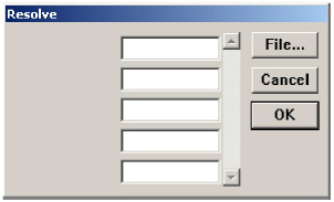
When using parametrics which contain many variables, create a text file to specify the variables and avoid entering them in the Resolve dialog box each time the parametrics are resolved.
Tech Note: To use a spreadsheet like Microsoft Excel for creating the text file, type in each cell the variable name and the value separated by a white space and export it as a text file.
Create a text file which alternates the variables and the values, using white space (SPACEBAR, TAB, or ENTER (Windows), RETURN (Macintosh)) between entries. Graphite assumes the first entry is a variable and the second is the value for that variable. The text file might look like the examples shown here or any other arrangements).
Tech Note: If text file contains more variables and values than it is necessary to resolve the geometry, Graphite automatically imports only the needed variables and values.
Using a Text File for Parametric Variables
1. Create the text file using any word processor or spreadsheet and saving it as Text only.
2. In Graphite select the geometry and parametric dimensions.
3. Choose Edit>Resolve.
The Resolve dialog box displays.
4. Click File to specify the values for the variables automatically.
5. Select the text filename.
The variables and values are read from the file.
6. Specify an anchor point, if necessary.
7. Click OK.
The geometry resolves accordingly.
Anchor the geometry by clicking the anchor point when the Resolve dialog box appears. For example, in a tutorial exercise in the Getting Started manual, parametrics were used to create the side view.
Using this side view as parametric geometry, it is possible to anchor the upper-right corner so that it remains aligned with the front view after resolution.
Changing the Dimensions to Actual Measurements
Once parametric geometry is resolved, the dimension notations continue to show variables and constants. To make the geometry reflect the actual measurements, edit the dimensions. Follow these steps to change a resolved parametric dimension to a real value:
1. Choose Edit>Selection Mask.
2. Highlight the four dimension types in the box on the left.
Only dimensions are selectable.
3. Choose Edit>Select All.
All dimensions are selected.
4. Choose Edit>Edit Objects.
5. Change the entry in the text data field to a # symbol.
6. Click Apply.
7. Close the Edit Objects and Selection Mask dialog boxes.
8. Click the Selection tool to cancel the effect of the Selection Mask.
If different types of dimensions need to be in different formats, select each type separately.
This section describes how to modify standard drafting practices to accommodate parametrics. It describes three examples with three topics to illustrate how to define parametric geometry completely.
• Define the geometry completely.
• Dimension all geometry.
• Relate all geometry.
• Do not include extraneous text.
• Return to the original part between tests.
Center lines require consideration if they are to be resolved properly.
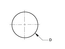
Creating the circle shown with two centerlines, parametrics can resolve the circle but not the centerlines because the endpoints of the lines are not defined.
A. Using the Pen Style, Center
Looking at this problem as a connect-the-dots problem, notice that the centerlines have no dots to define them.
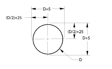
1. It is possible to construct the centerlines so their endpoints are on the circle, as shown here.
2. Include dimensions for the centerlines. The dimensions should be variables based on the diameter of the circle so when the diameter of the circle is specified, the centerlines are drawn relative to the diameter.
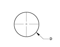
B. Using the Circle Center Line Tool
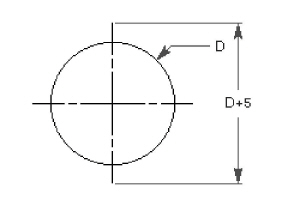
1. Use the Circle Center Line tool to place the center line on the circle.
2. Dimension the diameter of the circle and one of the center lines relative to the diameter. Dimension the center line from endpoint to endpoint or from the center of the circle to one endpoint of a center line.
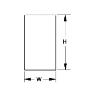
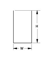
All parts of the geometry must be related.
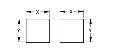
Both squares could be drawn by the parametric mechanism, but there is no way to determine their relative positions.
Add a constraint line and dimension between the squares to connect the dots.
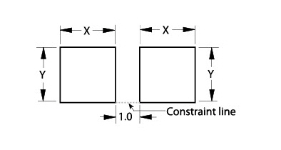
Additional Tips:
1. The added dimension is an example of using a constant value. A variable expression such as x+y can be entered for the constraint line.
2. Constraint lines are ordinary lines usually drawn with the Single Line tool. They can be any line style, but they should be different from the lines of the regular geometry. The Construction line style is a good choice.
3. Placing the constraint line and dimension on a layer (named Constraints), that layer can be hidden when plotting the drawing.
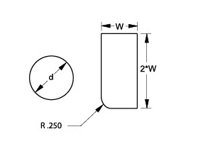
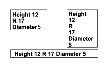
Dimension all geometry because the parametric mechanism does not understand text and cannot detect symmetry.
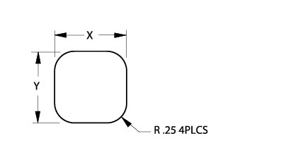
By dimensioning the radius of a filleted corner of a rectangle as R .25 4 PLCS to indicate four fillets, the parametric mechanism doesn’t understand 4 PLCS and doesn’t know the corners are symmetrical.
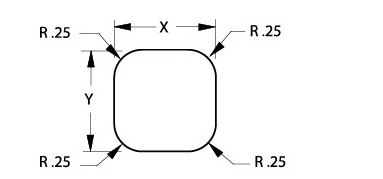
Dimension each fillet.
Return to the Original Part between Tests
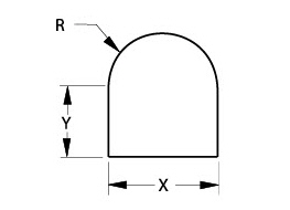
Resolving parametric geometry more than one time, unintentional constraints may be introduced that prevent the parametric function from returning to the original display of the part. Take the part below, for example.
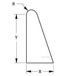
Resolving this geometry by specifying that R is half the measurement of X (R=X/2), the resolved geometry would appear as shown in the lower illustration.
Resolve this geometry only with the same X value of R * 2 because the undimensioned line is vertical, and according to the basic rules, vertical lines remain vertical.
If a value for R or X is used other than the R = X/2 relationship, the parametric mechanism would display this problem message:
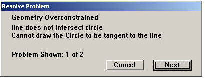
Use the Undo command to return to the original shape. It is also possible to solve this problem by changing the geometry.
This section illustrates problems that can be encountered when resolving parametric geometry. It provides examples and shows what caused the problem and how to solve it.
When resolving parametric geometry, problems which prevent resolution appear in a message box, stating the type and number of instances of the problems.

When a message appears, the problematic geometry appears as thick lines and individual dots. The lines indicate the geometry that the parametric mechanism can draw. Dots indicate unknown points. Click Next, and the next problem is shown. Examining of the relationships between the problems helps discern what must be done.
Important: Pay attention to single points. Remember, the parametric mechanism connects the dots. Frequently, one constraint or dimension can solve several problems at once.
The basic rules say that all geometry must be defined and every object must be related to some other geometry within the parametric definition. When geometry is overconstrained, it is related in more than one way, so the geometry’s specifications could be resolved to more than one answer.
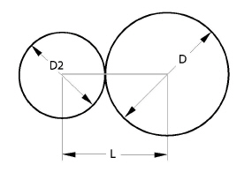
The diameters of the circles indicate the relationship between the circles adequately because the centerline remains horizontal and the circles are tangent to each other. The length variable causes the problem because the length between the centers of the circles may not correspond to the sizes of the connected circles. The centerline begins and ends at the centers of the circles.
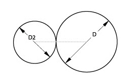
Delete the Length dimension.
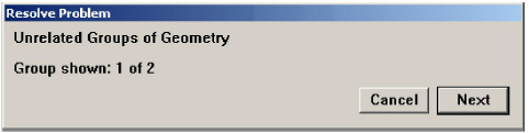
If not enough dimensions are provided, the parametric mechanism finds two or more groups of geometry, each of which is well-defined in itself, but not related to each other.
A simple example of this problem is illustrated on the left, where the short vertical line is not related to the rest of the geometry. Resolving this geometry, an Unrelated Group Problem message appears.
The first unrelated group appears in bold black lines. Click Next to highlight the second group.
This problem is like the two squares shown earlier. Only one group could be drawn. The parametric mechanism does not know how to relate the two groups.
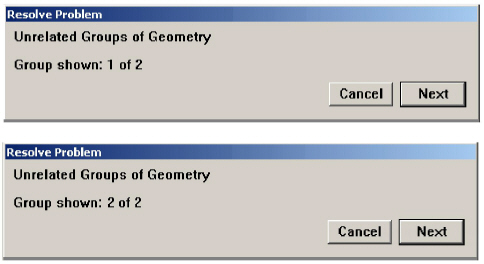
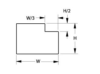
Decide how to relate the groups. Usually, there are many options to accomplish this. For this example, adding the dimension W/3 is one alternative.
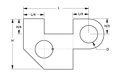
Unrelated Groups where One Group is a Single Point
A single point as an unrelated group is like a neon sign saying: The problem is right here!
The Resolve Problem message may display a single point, such as the point on the left hole of this example. That point is the endpoint of the circle.
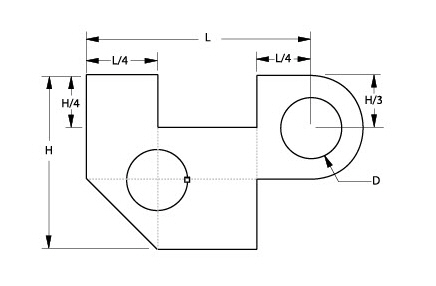
On closer examination, it is seen that the circle is not dimensioned. Therefore, the solution is to dimension the circle.
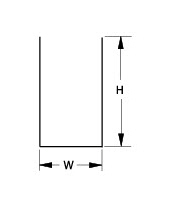
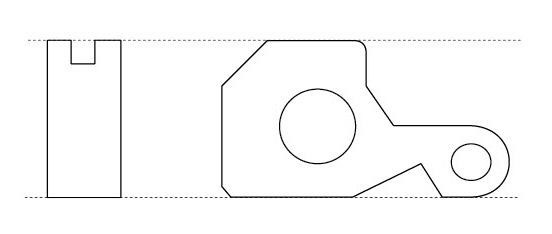
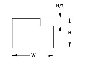
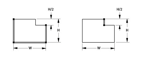
In this graphic, the height of the right side of the part is dimensioned. Assume that the height dimension applies to the right and left side. The parametric mechanism does not make that assumption.
There are three possible solutions to this problem:
1. The height can be dimensioned on the left.
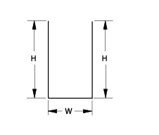
2. Draw a constraint line to close the opening.
3. Dimension the height from the top of the left line to the bottom of the right line. While this is not good drafting practice, it is very useful for parametric symbols.
Assumptions Involving Tangency
The parametric mechanism can identify tangent points but not the tangency of geometry.
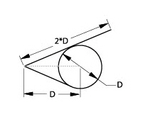
The endpoints of the lower line that is tangent to and ends at the circle can be determined. The upper line, however, is tangent to and extends beyond the circle and cannot be defined without more information.
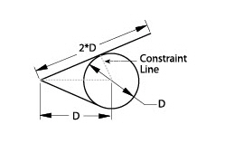
Here are three possible solutions to the problem:
1. Draw a constraint line from the center of the circle to the point of tangency for the line that extends beyond the circle, as shown here.
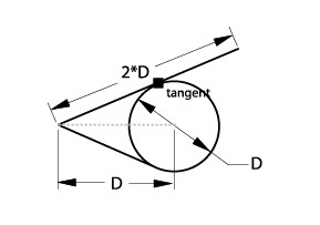
2. Use the Rotate tool on the Transformation subpalette to move the endpoint of the circle to the tangent point of the line that extends beyond the circle.
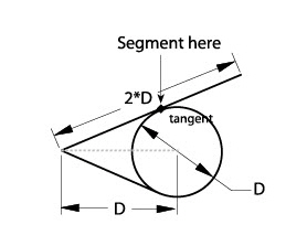
3. Divide the line into two segments which join at the tangent point.
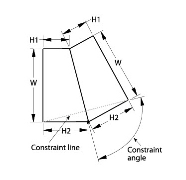
Relationships Involving Symmetry
Create geometry with a mirrored copy, the parametric mechanism cannot resolve and maintain the symmetry without more information.
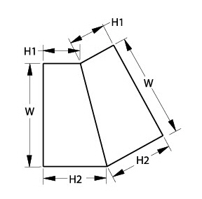
The problem message shows three unrelated groups: the trapezoid on the left and the two rightmost corners, as shown below.
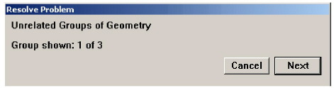
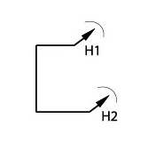
If parametrics swings an arc of the radius H1 and H2, it doesn’t know where the point is supposed to be on the arc. The point has a distance but no direction unless an angle dimension is added.
Single points that are considered a group provide a clue to the solution. In this example, the parametric mechanism does not know where those points are, relative to the original trapezoid. Solve the problem by adding a constraint line and angle dimension between that line and the mirror line.
This section illustrates two complex examples of parametric drafting. These examples combine the information provided in this chapter to display how to use the parametric mechanism.
Example—Departures from Standard Drafting
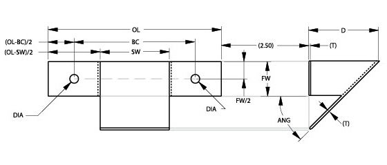
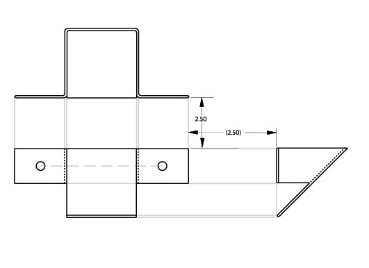
This example illustrates the parametric drafting practices that differ from standard drafting practices. The first illustration is the side view of an adapter without dimensions so its shape can be seen clearly.
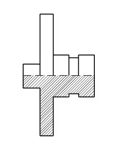
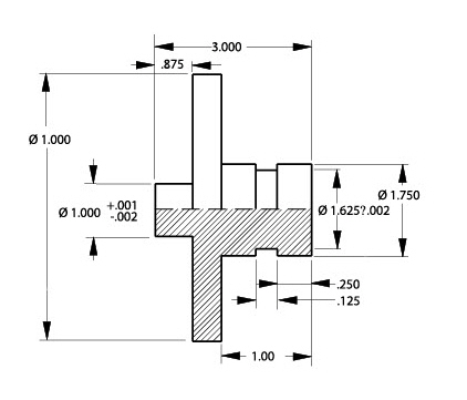
Here is the side view with typical dimensions added.
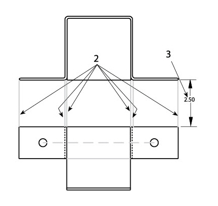
The illustration shows the side view with added constraint lines.
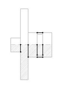
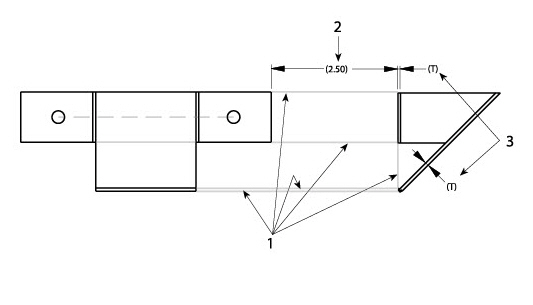
The next illustration shows the side view with numbered constraint lines.
1. The centerline does not extend beyond the geometry.
2. Constraint lines define the edges of the groove. Parametrics do not recognize non-touching colinear lines.
3. Constraint lines connect the endpoints of the upper and lower halves to relate the geometry. Parametrics do not recognize non-touching colinear lines.
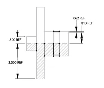
4. Four dimensions are added to relate the geometry to the centerline. Parametrics don’t recognize non-touching colinear lines.
The illustration below shows the completed parametric drawing.
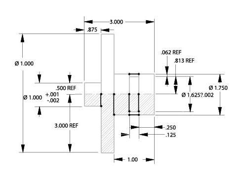
Additional Tips:
1. Place the additional information on a separate layer to hide the layer when plotting the drawing.
2. Using a yellow pen (which is hard to see against a white background) prevents confusing the additions with the actual geometry.
Example—Keep It Simple or Testing as You Go
When there are unconnected multiple views, the parametric mechanism can’t determine the relationships between them.
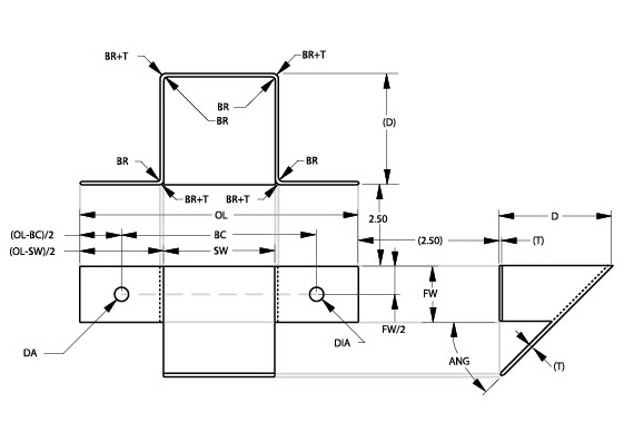
The coin chute example below describes the parametric drafting of three views.
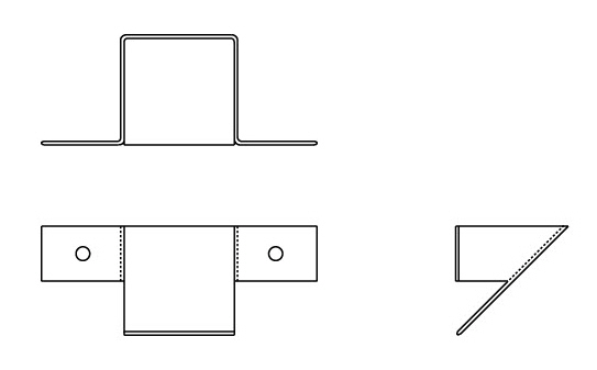
Dimension these views according to standard drafting practice, as shown.
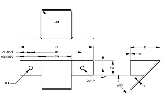
1. Construct and resolve one section at a time. Solve any problems with this bracket before moving on.
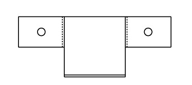
2. Add a centerline between the holes to maintain alignment.
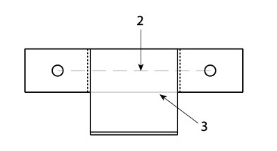
3. Add a line connecting the lower edges of the flanges to keep the lines colinear.
If the section below resolves without problems, go on to the next section.
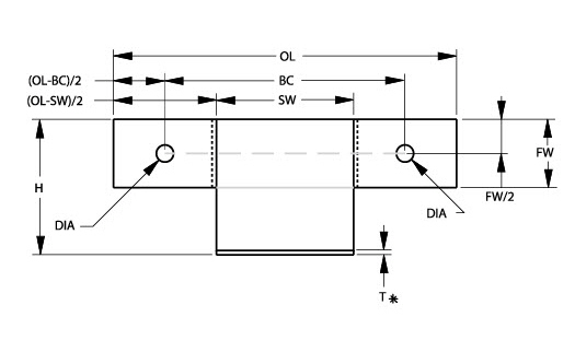
Once this view resolves properly, add the side view.
Since the side view determines height, delete the height (H) dimension and the lower thickness (T) dimension after adding the side view.
1. Add constraint lines to connect the geometry between sections.
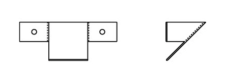
2. Add a dimension to specify the distance between the sections. (See the two box problem earlier in this section.)
3. Add extra thickness (T) dimensions since all geometry must be defined.
1. Dimension each fillet, as explained earlier.
2. Relate this section to the rest of the geometry.
3. Add a dimension to specify the distance between the sections.
Three sections are related as shown below.
This is the completed parametric drawing.
Parametrics and Grouped Objects
It is possible to create many objects. Group them and then treat them as a single parameterized object. There must be a framework on which the group sits. Dimension between two control points on the framework and then resolve the framework. The group changes accordingly, shrinking or expanding proportionately to the distance between the control points.
Create a spline and group it.
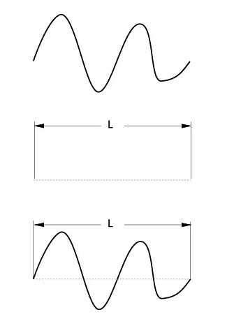
Then create a framework line between the endpoints and dimension the line.
When resolving for the length of the line (L), the spline changes accordingly.
Using Parametrics and Grouped Geometry
1. Create the geometry to be parameterized.
2. Select the geometry.
3. Choose Arrange>Group.
4. Create a framework on which the grouped geometry sits.
5. Dimension between two control points. It is possible to use only one variable per group.
6. Select the framework, the dimension and the group.
7. Choose Edit>Resolve.
8. Enter the value for the distance between the control points.
9. Click OK.
Including a dimension as part of the Group, the dimension changes when the Group is resolved. It is not used as part of the parametric solver.
Geometry can be grouped into a rigid body and then attached to the rigid body to parametric geometry in at least two points. Resolving the parametric geometry, the rigid body undergoes the same geometric transformation.
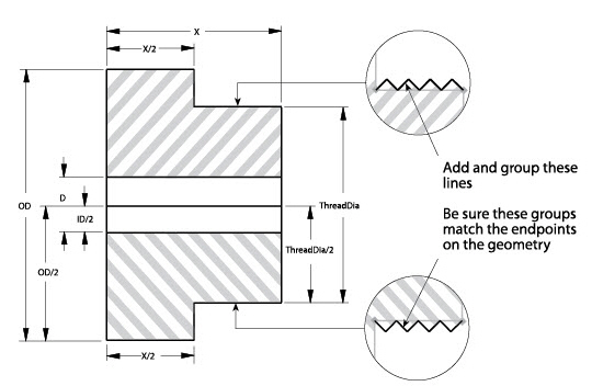
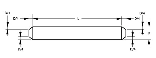
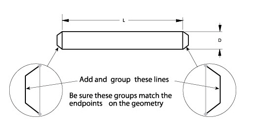
The following shows an example of using parametrics with grouped objects. Begin with a basic shape that resolves properly, as shown in the part below. Then add the thread groups. By resolving the part, the threads also resolve.
The next example shows, the usual method of parametric drafting followed by an example of how using parametrics with groups simplifies changes to the part.
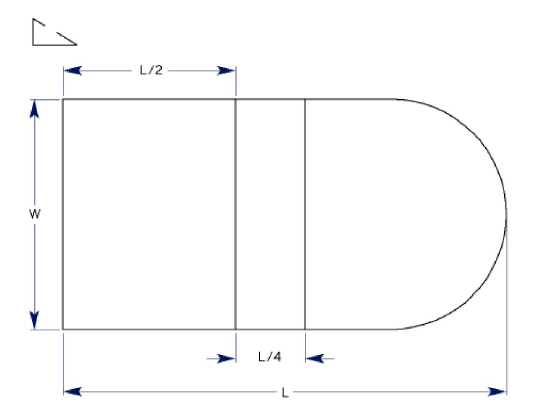
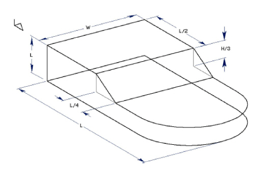
The parametric feature works in 3D with some restrictions. Consider its functionality as 2 1/2D since it functions properly in all planes parallel to the work plane.
The parametric mechanism has two phases. In the first phase, the parametrics ignore the z coordinates of the selected geometry and resolve the geometry as it does in 2D. Any dimension that is not completely in a plane parallel to the x,y plane is also ignored. In other words, the x and y coordinates are resolved and the z coordinates are not changed.
In the second phase, parametrics adjust the z coordinates, as necessary. All linear dimensions parallel to the z axis are examined and every point in the selected geometry is considered to define a plane parallel to the x,y plane. The dimensions in the z direction define the required distances between these planes. Unlike the first phase, in the second phase parametrics are very tolerant of missing dimensions. If the dimensions do not completely define the distance between any two planes, then the distance is not changed.
In phase two, any line or arc that does not lie in a plane parallel to the x,y plane is modified appropriately because the defining points are adjusted by the parametrics and the line or arc is changed accordingly. This includes all lines parallel to the z axis and any oblique lines at any angle to all three axes.
Parametrics deal with all geometry in the current work plane coordinates. Consequently, it is a good idea to set up a view that looks down the z axis of the work plane onto the x,y plane. In this way, it is possible to see what the first phase of the operation “sees.” This is particularly useful to encounter problems resolving parametric geometry. Errors in parametrics are shown in bold lines drawn in the x,y plane and independent of the z values of the highlighted lines. The easiest way to see this is to look down on the x,y plane by choosing Views>View The Plane.
In the drawing below, the first phase of parametrics will deal with only four dimensions W, L, L/2 and L/4. In the second phase, the H and H/3 dimensions are evaluated.