


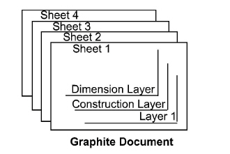
A document is a Graphite file. Whenever opening Graphite or choosing New from the File menu, a new document appears in the Graphite window.
The sheets and layers features add a great deal of flexibility to the documents. They show various parts of a document individually or as part of the whole. Each document has one or more sheets, like the sheets of paper in a set of blueprints, and each sheet is made up of layers which are hidden or displayed as needed.
New users are sometimes too busy learning about Graphite to think about how to organize the drawings. Consider organization early, however, since eventually there will be a large number of drawings. Organization is particularly important for sharing files with other people.
The following topics are covered in this chapter.
• Using Documents, Including Opening, Recent File List and Saving
• Drawing Scale and Paper Size
• Forms
• Printing or Plotting a Drawing
Using Documents, Including Opening, Recent File List and Saving
A drawing can be a simple part or a complex assembly. A new document opens as Untitled and remains untitled until it is saved. Saving a drawing is explained later in this chapter.
The commands used to manipulate documents are in the File menu and in the Window>General palette.
CTRL+N (Windows); z+N (Macintosh)
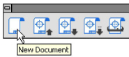
This command in the File menu, or in the Window>General palette, creates a new Graphite document.
The new document has no name (the title bar shows Untitled 1), and is set with the default options, such as pen style or grid display.
Opening more than one new document, the subsequent documents are numbered sequentially until named upon saving.
Open files using the Open command in the File menu or in the Window>General palette in the program or by double-clicking on the file to launch the program and the file.
CTRL+O (Windows) ; z+O (Macintosh)
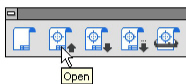
The Open command in the File menu, or in the Window>General palette, opens existing Graphite documents, DWG/DXF, PDF, and EPS files. The document appears in the drawing area maintaining the same settings as the last time it was saved.
The dialog box specifies the document name and folder as necessary.
Tech Note: Use the Import command to bring in drawings of other format types, such as IGES, or ASCII text.
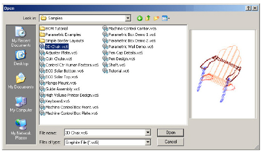
1. Choose File>Open or click the Open (second) icon in the Window>General palette.

The dialog box appears.
The current folder displays the files and/or folders contained within.
2. Display the appropriate folder containing the document to open.
The Vellum Graphite file extension is .vc6, where v is for Vellum and c6 is the chemical abbreviation for Graphite.
3. Click the file name to open in the list box.
4. Click OK.
Opening a DWG/DXF, PDF, and EPS Files
Directly open other files formats such as DWG/DXF, PDF, and EPS.
Opening a File when Graphite is not Running
Open a file and launch Graphite at the same time by double-clicking on the file. The program launches automatically and the file opens. By using this technique, no untitled file opens.
Another way to access files that were opened recently is through the Recent File List that appears at the end of the File menu. This list contains the names and paths of recently opened Graphite files.
To open a file from the Recent File List, simply select the file from the File menu. If the file has been moved since it was last used and the path is no longer accurate, Graphite provides the standard Open dialog box to locate the file.
Tech Note: The number of files contained in this list can be set in the Graphite.ini file (Windows) or the recent list file in the User’s Scripts folder (Macintosh). For more information, consult Basic Environment Settings.
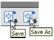
Save a drawing by choosing File>Save, or Save As, or clicking the corresponding icons in the Window>General palette. The file is stored on the computer in the folder specified.
CTRL+S (Windows); z+S (Macintosh)
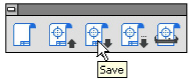
The Save command in the File menu, or icon in the Window>General palette, saves the current Graphite document to its original folder. To save it to a different folder or with a different name, choose Save As. If the document has not been saved previously, the Save As tool dialog box appears automatically, requesting the name and the folder in which to save it.
If the document was named and saved before, a brief message appears when choosing Save, and the program pauses while it updates the information.
Save frequently. Even though the drawing appears on the screen, it is not stored on the disk until saved. Hours of work can be lost because of a power failure. It is also important to save before performing any intricate, multistep maneuver. In that way, if the result is not exactly what it is hoped, abandon the file by closing it without saving.
Tip: Use AutoSave so that Graphite automatically saves the work. Choose Layout>Preferences>AutoSave.
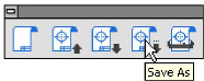
The Save as command in the File menu, or in the Window>General palette, saves the current document. A dialog box appears in order to name the current document, give it a different name, or save it to a different directory.
Saving in the Current Directory
1. Choose File>Save As or click the Save As (forth) icon in the Window>General palette.
The Save Drawing As dialog box appears.
2. If necessary, display a different folder.
3. Type the name to use in the File name data field.
4. Either press ENTER (Windows), RETURN (Macintosh) or click OK.
The Vellum Graphite file extension is .vc6, where v is for Vellum and c6 is the chemical abbreviation for Graphite.
Use the Save As command to make a backup of a document.
It is always a good idea to make a backup of the file in case you want to return to the original version after making many changes. Choose File>Save As and save the file with another name. It’s possible that periodic backups are made of the directories by you or your IT department, and you can go back to a previous version that way.
This command is found under Layout>Preferences and directs Graphite to save a backup copy of the work periodically. If the computer crashes for any reason, the work done up to the last AutoSave is recoverable.
In the AutoSave dialog box turns AutoSave On or Off, and specifies the time interval (in minutes) between AutoSaves. At the specified interval, Graphite creates an AutoSave file with the base of the original file name and the .SAV extension. AutoSave prompts for a file name before creating an AutoSave file of untitled documents (created by using the New command from the File menu). If a file name is supplied, this file name is associated with the document and the AutoSave file. If Cancel is clicked, AutoSave skips that document, but the prompt appears again at the next AutoSave interval.
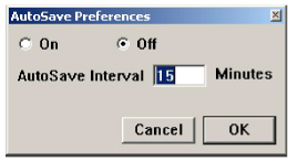
1. Choose Layout>Preferences>AutoSave. The AutoSave dialog appears.
2. Switch AutoSave On or Off. The default setting is off.
3. Specify the time interval for AutoSaving in minutes in the AutoSave Interval data field. The interval can be from 1 to 60 minutes; the default setting is 15 minutes. An interval of 0 or less is equivalent to turning AutoSave off.
4. Click OK.
If AutoSave is on the work is automatically saved for the specified time interval. To save these settings permanently, choose Layout>Preferences>Save Preferences. Close any open untitled files before saving the preferences, otherwise, with AutoSave On, the Save As command continually appears.
CTRL+F4 (Windows); z+W (Macintosh)
The Close command in the File menu closes the current Graphite document (the one displayed in the top window). If other Graphite documents are open, they remain open when closing the current document. If any changes were prompts for each made since the last time the current document was saved, a dialog box displays in order to save the changes. Close the document with or without saving the changes.
For Windows, close the document by double clicking the Control menu at the upper left corner of the title bar. For Macintosh, click the Close button once at the upper left corner.
Exit Command (Windows) or Quit Command (Macintosh)
CTRL+Q (Windows); z+Q (Macintosh)
The Exit or Quit commands in the File menu closes Graphite. If changes were made since the file was last saved, a dialog box displays in order to save the changes. If more than one document is open, an alert message displays in order to save unsaved documents.
Graphite automatically organizes files using the Directory function in Preferences. When opening, saving, importing and exporting files, Graphite goes to the directory or folder specified.
1. Choose Layout>Preferences>Directory.
The Directory Selection dialog box appears with four fields for specifying the directory location.
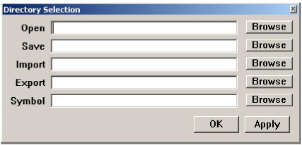
2. Enter the directory path in each data field. Either type the path or browse the computer for the folder and have the path entered automatically.
To browse, click on the Browse button and locate the desired folder.
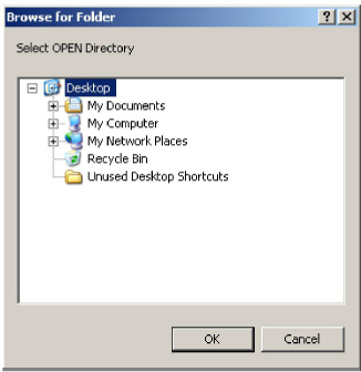
Click OK.
The path appears in the selected data field of the Directory Selection dialog box.
3. Repeat step #2 for all of the directories specified.
4. Click Apply to save the settings and close the dialog box.
Before beginning a file translation for Graphite, establish a clear purpose for any particular translation. Consider if the translated data must be edited or just viewed and/or printed. If it is to be viewed or printed, use the Graphite ShareTM utility available FREE on the Ashlar-Vellum web site. Graphite Share opens, views, prints and exports Graphite and older Vellum 2D/3D files. Send Graphite Share to a client or manufacturer free of charge along with a Graphite file. Share allows them to export the file themselves, experimenting with the file format that works best for their needs.
On the other hand, if the translated data must be manipulated and saved, consider if the target application that can handle the data being translated to it properly, such as multiple sheets in one file.
Remember that re-importing a file successfully into the original format neither proves nor disproves its translation accuracy.
Older versions of Vellum had difficulties with metric-to-English conversions. These were addressed in Graphite v6, but be aware of the issues if any archive files need to be converted.
Use Zip or Stuff-It to compress files before emailing. Using an email program’s built-in compression has unreliable results on graphics, often converting them to text files. This is especially true if emailing a file from a Mac to a Windows-based system.
The reasons to use the import and export features of Graphite are:
• Bringing a document in from another application to work on in Graphite.
• Saving a document in a format other than Graphite for use with another application.
• Importing or exporting text to or from a Graphite document that's an ASCII text file.
Graphite offers a wide variety of options to accomplish this.
This command in the File menu imports a document and places it in the current model. The names of documents in a format Graphite can read are displayed in a dialog box that works like the Open dialog box.
Tip: When importing into Graphite, choose Arrange>Zoom All to see the imported geometry.
1. Choose File>Import.
A dialog box appears similar to the Open dialog box.
2. Windows Select the file type to import from the Files of Type list box. The list box shows all files of the selected type available in that folder.
Macintosh Skip to the next step.
3. Double-click the File name to import.
The Import dialog box appears.
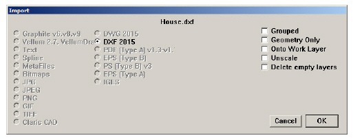
4. Specify import options.
5. Click OK.
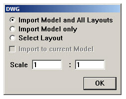
If you are importing DXF/DWG files, scale factor can be set prior to importing. Specify it in the window that appears and click OK.
The file appears in the drawing area. To save the file in its original format after editing, choose the File>Export.
Tip: To ungroup the imported geometry choose Arrange> Ungroup.
The file formats Graphite imports are listed below:
|
Using the Import command, Graphite detects the format of the document and displays a dialog box showing the format and asking how to bring the geometry into Graphite.
|
While Graphite offers high visual fidelity for dimensions and text in DXF format, if the goal is to import or export archive drawings, preserving the text and dimensions, use a free copy of Ashlar-Vellum Share or buy Adobe Acrobat instead.
DXF files do not always specify units. Be sure to set Graphite to match the source file prior to importing it. Also, because individual users customize their systems, there is often difficulty in translating fonts, line weights and patterns, dimensioning styles, hatch patterns and custom symbols. Be sure these are also present on the destination system.
When importing a DXF file, the geometry is constructed according to the units set in Preferences when choosing the Import command. Be sure to set the appropriate units before importing DXF geometry.
Importing ASCII Text from Another Document
1. Choose File>Import.
The Import dialog box appears.
2. Select the filename to import.
3. If Text is not selected, click the Text button.
4. Click OK.
The text appears in a text box in the drawing.
Importing a text file that contains the coordinates of a spline, Graphite creates the spline according to the imported coordinates.
1. Select File>Import.
Graphite displays the standard Open dialog box.
2. Select a text file that contains the coordinates for the spline.
The Import dialog box displays.
3. Specify the import option Spline.
4. Click OK.
Graphite begins creating the Spline.
Creating a Text File for Importing a Spline
1. Use a text editor, a word processor or a spreadsheet to create a text file.
2. Input X, Y and Z values for the spline coordinates.
The text file should be tab or space separated. Each line ends with a return. Line feeds after each return should have no effect.
The text file should conform to the following columnar format:
|
Specify decimal coordinates as well:
|
Be sure to press ENTER (Windows) or RETURN (Macintosh) after the last coordinate, if Graphite will not import the coordinates specified in the last line.
3. Save the file as Text only and import into Graphite to create the spline.
How Importing Affects Some Objects
It is difficult to exchange data between different graphic programs because each program defines geometric objects differently. All entities created in one program may not translate accurately or at all depending on what the program supports. The following lists are specifics about entities for two translators.
|
|
The Export command in the File menu saves a document in the format specified.
1. Choose File>Export.
The Export dialog box appears.
2. Click the desired file type. To export only selected objects on the screen, rather than the entire document, click Only Selected.
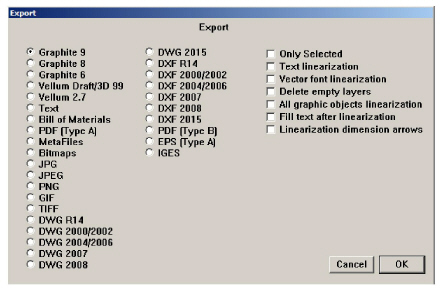
3. Click OK. The Export file dialog box appears.
The Export dialog box is identical in both appearance and function to the Save As dialog box. For Windows, filename extension indicates the type of export file.
The following file types can be exported:
|
By specifying Only Selected, only the selected objects in the drawing are saved in the export format. If Only Selected is not specified, all objects are saved for export.
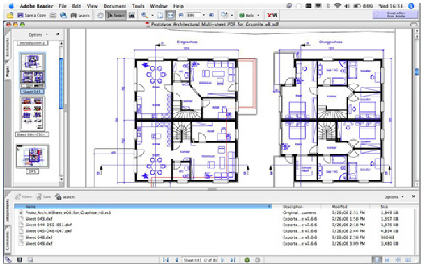
CAD files do not archive or email well and PDF files don’t allow for further CAD editing or machining. It is possible, however, to create multi-sheet PDFs directly from within Graphite and embed .dxf and .vc6 files directly in the file.
PDFs email easily and they accurately reproduce fonts, line styles and patterns, but allow no access to manipulate the source data for editing, printing or manufacturing.
Graphite’s built in PDF writer has several advantages over the PDF maker built into the operating system. In Graphite it is possible to create multi-sheet PDFs drawn from multiple models in the same file. Optionally embed a Graphite file or a DXF export file directly in the file. Everything for an entire project can be emailed, displayed and archived.
Use Adobe Acrobat to further enhance the file, inserting and replacing pages, commenting and marking changes or tracking revisions.
1. Chose File>Export.
2. Select PDF from the Export dialogue box and click OK.
3. The Save File As dialogue box appears. Enter the name and location to save the PDF.
4. The PDF attachment box appears. Select which file to include and click OK.
How Exporting Affects Some Objects
It is difficult to exchange data between different graphic programs because each program defines geometric objects differently. Even though the DXF and IGES formats standardize this exchange, some objects do not transfer exactly. For example, crosshatching is no longer associative although it does appear in exported files. The following table tells what to expect when exporting Graphite objects.
|
|
|
All geometry is exported as individual elements, except in the following circumstances:
• Fill geometry
• Grouped geometry
This translator shares data between Graphite and other EPS applications. It was optimized for Adobe Illustrator 5.0J but works with other applications that support the EPS file format. This translator imports a postscript file into Graphite (text is not translated) and exports drawing data.
In postscript's expression, drawing data is described as a “path.” 2D drawing data is expressed by the values given for the path from the startpoint to the endpoint. Straight lines and Bezier curves create such paths.
For example, a circle contains the following components:
• 4 connected Bezier curves (in Adobe Illustrator the path is structured by anchor points (startpoint, centerpoint and endpoint) and segments). If the circle is created using one tool, then the anchor points are connected.
• Path width: user-defined units or points (1pt=0.35 mm)
• Path Color: user-defined
• Fill inside Startpoint~Endpoint: user-defined
• Fill Color: user-defined
The CADAM BMI translator shares data between Graphite and CADAM. The translator converts this data, using the BMI format, into a neutral file format of CADAM.
All recognizable entities will be converted with their attributes. For unrecognizable entities, only the shapes will be converted.
The translator works according to the graphic below.
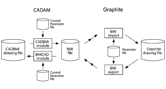
The VelBmi.ini file is the Control Parameter file. This parameter file is used in the translation of the geometric entities in the drawing.
Tips for the Best Possible Translation
In general, it is recommended to show all the layers before exporting from Graphite or any other CAD package to know what objects are exporting.
• Graphite was designed to export only the current model. If there are Detail Views in the file, flatten them with the Flatten View command found in the Views menu. If dimensions already appear in the detail view and the view scale is set to 1, group the dimensions and geometry together before flattening the view. This brings the dimensions across to the current model for Export.
• Graphite supports 256 layers. If a DXF file contains more than 256 layers, the geometry that is on the additional layers is automatically placed on the current work layer in Graphite. If this is not desirable, reduce the number of layers to maximum of 256 in the application where DXF file is being created.
• Attributes in an AutoCAD file do not come into Graphite as text because Graphite does not support that entity type. To bring the attributes into Graphite via DXF, convert those attributes to Text before Exporting from AutoCAD.
• If, when translating to AutoCAD, the line patterns do not seem to come across or are distorted (too big or too small), change the AutoCAD variable LTSCALE to a smaller number to display the line patterns at an appropriate scale.
• With some angular dimensions, the arrow may be displayed in AutoCAD in the wrong direction (pointing towards the text rather than towards the extension lines). If this happens, execute the DIM command in AutoCAD, select the affected dimensions, and use the UPDATE command to display the arrow correctly.
• To export from Graphite to Illustrator, use the EPS format. Be aware that dimensions, text, and .pict and .bmp images are not supported by EPS in this process. Remember that EPS does not support 3D data. It will translate all data to the top view, unless the 3D data is flattened before exporting as EPS. If text and dimensions are needed for Illustrator, export using the DXF format or print to Post Script. Usually the easiest way to get simple data into Illustrator is to highlight it in Graphite, then copy it to the clipboard and paste it into Illustrator.
• We recommend using DWG for translating data between Graphite and Pro/E.
• DWG is the preferred method of translation between Graphite and SolidWorks.
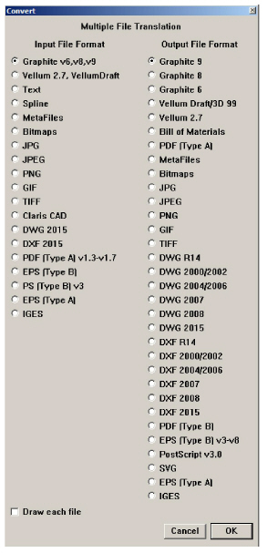
This command in the File menu starts the Convert batch translator importing and exporting multiple files in an unattended mode. It imports all files of the same type from one folder and saves these files in the selected format into a destination folder.
1. Create two folders.
One folder is used to store the original files (the FilesIn folder), the other folder stores the converted files (the FilesOut folder).
2. Copy all files to convert into the FilesIn folder.
3. Select the File>Convert.
The Multiple File Translation dialog box appears.
4. Select the file type being translated from the Input File Format column.
5. Select the file type being translated from the Output File Format column.
6. Check the Draw each file option, if desired.
Mark this option to see each file during the conversion process. If this option is not selected, Graphite opens a blank drawing window, performs the conversion, closes the blank window and repeats the process for each file in the folder.
For large drawings or large quantities of drawings turning off Draw each file speeds up the operation.
7. Click OK.
The Open file dialog box displays.
8. Open the folder (FilesIn) that contains the files to convert.
9. Select a single file and click Open.
The selected file must be of the same type as was selected for Input File format or Graphite generates an error message.
10. Select a destination folder (FilesOut) for the translated files or create a new one.
Specify a new extension to identify the converted files (it is reasonable to use the standard file type extension like .dxf for DXF files or .igs for IGES files. This is not necessary for the Macintosh but may help in file organization.
Graphite will convert every file from the Input folder that is of the same type.
Select a Graphite file in the Input folder, and requested convert to DXF, Graphite converts every Graphite file in that folder to DXF, and places those DXF files in the Output folder selected. If the folder also contains IGES files, they are not translated.
Specify DXF as the Output file format, Graphite asks once to convert thick lines to be Polylines. Whatever is specified is valid for all DXF Files in that folder.
Whether designing or drafting a highly detailed blueprint, create the geometry at its actual size. Graphite enables constructing the part using full-scale specifications and then setting the visual scale of the drawing. In this way, the part dimensions to its true-to-life measurements. Drawing at full scale has the following advantages:
• Scaling mistakes are eliminated.
• Dimensions are automatic (dimension manually if not drawing at full scale).
• Associative dimensions update when the object is edited (manual dimensions do not).
• The size relationship of imported parts is compatible.
• Calculations for 2D analysis are accurate. (See 2D Analysis for more information.)
Once the project is drawn, it can be dimensioned, scaled it visually, and sized to fit into a standard drawing format, if needed. The actual size of the geometry remains constant unless edited.
When opening a new Graphite document, the drawing area is a sheet that is infinitely large to design anything at full size. For a simplistic example, here's how to draw and view a line 83 feet long:
1. Draw a line, specifying 83' for the length.
The line extends off the screen.
2. Choose Arrange>Zoom All. The entire 83 foot line is visible on the screen.
Using the draw to scale/Zoom All method, create accurate full-scale drawings which are displayed at the magnification chosen.
Reminder: The actual size of an object is not affected by zoom magnification or reduction.
Scaling Line Patterns and Crosshatch Patterns
If the unscaled construction is very large or very small compared to the size of added text and dimensions, line patterns and crosshatch patterns are inappropriately sized. By setting the scale for the drawing with the Drawing Size or Sheet Into View command, line patterns and crosshatch patterns are automatically scaled with the inverse scale factor specified. The patterns appear at the appropriate size for the view scale of the geometry.
Tech Note: Zoom All magnifies or reduces all objects on a drawing to fill the screen—regardless of how big or small the objects are.
If drawing objects that are scaled visually, text, dimensions, line patterns and crosshatch patterns behave, when scaled, differently than the geometry created. While geometry always scales with the specified scale factor, text and dimensions scale with the inverse scale factor set with the Drawing Size or Sheet Into View command.
While the inverse scale factor applies immediately to line patterns and crosshatch patterns as described in the section above, the inverse scale factor applies only to future text and dimensions added after scaling. Existing text and dimensions scale with the same scale factor as the object geometry. A 12 pt. text that was created at a 1:1 drawing scale is 24 pt. on a page printed at a 2:1 scale. The size of the text does not change relative to the other geometry in the file.
To keep the text size specified before scaling, choose the Keep Text Size and Keep Dimension Text Size options in the Drawing Size dialog box. This changes the size of the text relative to other geometry in the file. For example, 12 pt. text that was created at a 1:1 drawing scale is still 12 pt. on a page printed at a 2:1 scale. The size of the text is half as small as before changing the drawing scale, relative to other geometry.
Another method of controlling text size and dimensions while scaling is to calculate the needed text size manually as shown in the following example.
When calculating the text size for scaling manually the rule is: set the text size to the inverse of the scaling factor. (The text size affects both text and dimensions.) In that way, the text elements of the drawing are proportional with the size of the geometry.
For example, if an assembly is 83 feet wide, scale that assembly 1:100 (a scale factor of .01) to place it in a drawing format. This requires using text that is equally large to read it visually when scaling the drawing. The final text to be .156 inch in height, specify 100 x .156 for the text size in the drawing. With the manual calculation make this specification before beginning dimensioning or annotating.
Tech Note: When scaling smaller, multiply the text size by the scale factor. If scaling larger, divide the text size by the scale factor.
Scaling Text and Dimensions Manually
1. Choose Text>Size>Other.
The dialog box displays the measurement of the text.
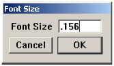
The Font Size is set to .156 inch.
2. Click after the entry in the data field.
The text cursor blinks in the data field.
3. Enter *100 and click OK.
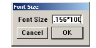
Subsequent text and dimensions are one hundred times the original size, or 15.6 inches. When adding dimensions, the text size is appropriate for the part.
When the design is ready to be detailed with line patterns and dimensions, or to print or plot the design, scale the view of the drawing to fit the paper used.
Specify a printer or plotter, the paper format and orientation, and then the drawing size for the specified format.
Tech Note: The relationship between the object and the text should appear normal when zoomed. If it looks right, it is right.
Graphite’s built in PDF writer has several advantages over the PDF maker included into the operating system, such as embedding source and other target export files. It also supports multiple sheet drawing.
Print Setup (Windows); Page Setup (Macintosh)
The Print Setup or Page Setup command in the File menu sets the page size, orientation and other options.
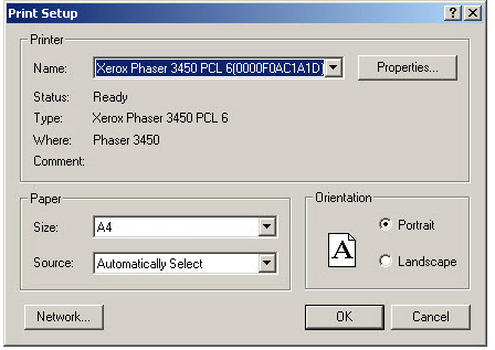
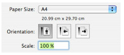
1. Select the plotter or printer.
2. In the Paper Size menu, select the paper size.
3. Specify the orientation.
The Drawing Size command in the Layout menu shows the size of the maximum plotting/printing area relative to the drawing. It also specifies the scaling of the drawing so it fits the paper size and orientation set by the Print Setup (Windows) or Page Setup (Macintosh) command. The Drawing Size window has two tabs: Printing and PDF Exporting.
Setting Up the Drawing Size for Printing to Paper
If the geometry is larger than a standard piece of paper, or so small that it would be impossible to use it at full scale, set the Drawing Size. In many cases, it may be desirable to use a standard drawing scale (such as 1/4 inch = 1 foot) for the drafting project.
1. Choose Layout>Drawing Size. A dialog box appears.
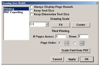
2. Select Printing from the list.
3. Specify the scale, using one of three methods below as necessary:
• Click the Drawing Scale data field and enter a scale ratio (Plotted Size: Actual Size). Enter real values, such as 0.25'' : 1', which Graphite converts to 1:48. Click Apply to see the effect of the scaling.
• Or press the arrow beside the Drawing Scale data field and choose one of the standard ratios from the menu. Click Apply to see the specified scaling.
• Or click the Scale Font from PDF button to copy the text scale from the PDF Exporting tab if preferred. Make sure that the Keep Text Size option is checked to enable this functionality. Click Apply to see the result of scaling.
Tip: When scaling the drawing, text and dimensions behave differently from the geometry created as described under the Scaling Text and Dimensions section earlier in this chapter.
The Cancel button on the Drawing Size dialog box doesn’t abort changes if Fit or Apply were chosen first.
If a specific scale is not needed, click Fit to scale the drawing to fit the paper.
With any of these methods, the geometry itself does not change scale on the display; it only changes visually, not physically.
4. When printing multiple sheets and taping them together, follow the directions for Tiled Printing later in this chapter.
5. Click OK.
Setting Up the Drawing Size for Exporting to PDF
PDF is basically electronic or virtual paper with some of the same issues as actual paper. There are separate settings for Exporting to PDF because sometimes you’d like to use a different paper size than is supported by your printer.
Note: This is NOT the same as Print to PDF. You may still Print to PDF by configuring PDF printer software from an appropriate supplier.
1. Choose Layout>Drawing Size. A dialog box appears.
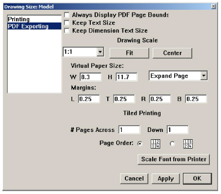
2. Choose the PDF Exporting tab.
3. Specify the width and height in the W and H data fields or click the down arrow in the data field on the right to choose one of the predefined sizes. Set the margins for the left, top, right and bottom edges of the page in the L, T, R, B data entry fields.
• Click the Drawing Scale data field and enter a scale ratio (Plotted Size: Actual Size). Enter real values, such as 0.25'' : 1', which Graphite converts to 1:48. Click Apply to see the effect of the scaling.
• Or press the arrow beside the Drawing Scale data field and choose one of the standard ratios from the menu. Click Apply to see the specified scaling.
• Or click the Scale Font from Printer button to copy the text scale from the Printing tab if preferred. Make sure that the Keep Text Size option is checked to enable this functionality. Click Apply to see the result of scaling.
Tip: When scaling the drawing, text and dimensions behave differently from the geometry created as described under the Scaling Text and Dimensions section earlier in this chapter.
The Cancel button on the Drawing Size dialog box doesn’t abort changes if Fit or Apply were chosen first.
If a specific scale is not needed, click Fit to scale the drawing to fit the paper.
With any of these methods, the geometry itself does not change scale just the display; it only changes visually, not physically.
4. When printing multiple sheets and taping them together, follow the directions for Tiled Printing later in this chapter.
5. Click OK.
Setting the Visual Scale with the Sheet Into View Command
Once a full-scale part has been drawn and dimensioned, then create a visually-scaled view of that part. The Sheet Into View command performs the details of this operation automatically.
Referral: An exact description of the Sheet into View command is in the Tiled Printing section.
1. Choose Arrange>Zoom All.
All objects are displayed on the screen.
2. Choose the Views>Sheet Into View.
3. Enter the scaling value in the Scale data field of the Sheet Into View dialog box. Figuring this value is similar to drafting on paper, determining which scale to use so that the finished part fits on the paper size.
4. Click OK.
The part is now in an independent view, scaled as specified.
Scaling does not change the actual dimensions of the part. Verify this by selecting an object and then looking at the specifications of that object in the Edit Objects dialog box.
Tech Note: The location of the Layout file for the drawing formats varies with the version of Graphite, the platform and the version of the operating system. It can be found under User, Workgroup, System (Mac only) and/or Program. For specific information on your version try the knowledgebase in the Support Center on the website at www.ashlar.com.
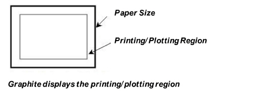
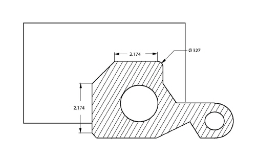
Select Layout>Drawing Size and then click Always Display Page Bounds. A gray rectangle appears in the drawing area. This rectangle represents the printing/plotting region of the page to show how the drawing fits the paper. The plotting region is smaller than the actual page size because most printers and plotters cannot plot to the edge of the paper. For the plottable outline not to show all the time, uncheck Always Display Page Bounds
.
Tech Note: It is only possible to pan when the Drawing Size dialog box is open. Once closed it is no longer possible to adjust the boundaries through panning.
The size of this region is based on the paper size and the printer or plotter drive currently selected.
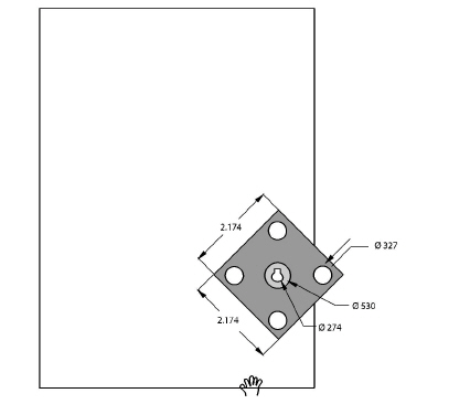
When the boundary of the printing/plotting region appears, drag the boundary rectangle around the drawing area with the Hand pointer, as shown above. The cursor becomes the Hand pointer when the cursor is moved outside of the dialog box.
To change the paper orientation while the Drawing Size dialog box is visible, choose File>Print Setup (Windows) or Page Setup (Macintosh) and enter the specifications. The new specifications appear in the drawing area.
When using a printer rather than a plotter, it is possible to tape pages together to get a larger drawing than laser printers allow. Specify the layout for those pages by choosing Layout>Drawing Size.
1. Choose Layout>Drawing Size.
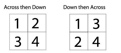
2. Specify the number of pages Across for the final drawing.
3. Specify the number of pages Down for the final drawing.
4. Specify the order for printing the pages (Across then Down or Down then Across).
5. Click Fit.
6. Click OK.
The drawing scales to fit the number of pages and layout as specified.
The Preview Layout command in the File menu shows the size and orientation of the printing area specified in Print Setup (Windows) or Page Setup (Macintosh) by displaying a black border. If a printing/plotting size is not specified, the default size is used. To remove the page border display, select the command again or simply select a tool from the tool palette.
If the drawing does not fit the paper size, choose Layout>Drawing Size.
When a part is complete and ready to be placed in a formatted border, Graphite provides many options. Not only can all drawing formats be modified in the Layout folder, but it is also possible to create your own drawing formats and design layouts as well.
Graphite distinguishes between Drawing Formats and Design Layouts. Drawing formats contain the border line of the drawing, the cutting line and a Title block for entries such as name and scale of the drawing. Design layouts contain a border and detail views.
• Drawing formats have to be created for each paper format such as A, B, C or D and for both paper orientations Portrait and Landscape.
• All drawing formats found in the Layout folder are designed for Plotter devices, where the cutting lines correspond exactly with the dimensions of the selected paper format (for example 30 x 40 inch for the D Format) and the Border line is offset inside by a half inch according to the ANSI standard.
• When using these plotter formats for a laser printer it is necessary to adjust them to the printing area of the printer, since they often differ from printer to printer.
• Design layouts contain, in addition to the drawing format, one or more detail views that may display with the Sheet Into View command the content of a drawing at different view angles and scale factor.
Tech Note: The location of the Layout file for the drawing formats varies with the version of Graphite, the platform and the version of the operating system. It can be found under User, Workgroup, System (Mac only) and/or Program. For specific information on your version try the knowledgebase in the Support Center on the website at www.ashlar.com.
Graphite places Standard Drawing Formats using two different commands:
• The Import command in the File menu.
• the Sheet Into View command in the Views menu.
If a part is placed in a detail view and visually scaled, it is possible to import a standard drawing format (either one of those supplied by Ashlar-Vellum or a custom format) in preparation for printing or plotting. Since the format should be full scale, it must be imported onto the sheet outside the view because the detail view is scaled and the sheet is not.
1. Choose Layout>Drawing Size to scale the drawing.
The Drawing Size dialog box displays.
2. Mark the Always Display Page Bounds option to compare the true size of the drawing with the displayed printing area of the drawing format.
3. Choose the File>Import.
The Import dialog box displays.
4. Mark the unscaled option.
5. Select a desired drawing format under your language in the Layout Folder on your system. See the Tech Note on locating the Layout Folder. For example:
ViewB.vc6 (Windows) or a Format B & View (Macintosh) where 1View stands for one detail view and B for the paper format.
Important: Ignore the number of detail views since they are only important when using the Sheet Into View command.
6. Click OK.
Tech Note: The location of the Layout file for the drawing formats varies with the version of Graphite, the platform and the version of the operating system. It can be found under User, Workgroup, System (Mac only) and/or Program. For specific information on your version try the knowledgebase in the Support Center on the website at www.ashlar.com.
Using the Sheet into View Command
With the Sheet Into View command, Graphite imports not only a drawing format but also displays the drawing at the specified scale in one or several detail views, depending on the selected design layout.
1. Choose the Sheet Into View command in the Views menu.
The Sheet Into View dialog box displays.
2. Select the desired drawing format from the Layout list box, such as:
B Landscape 4 Views.vc6
where B Landscape stands for the paper size and orientation, and 4 Views designates the number of detail views.
3. Enter the desired scale factor in the Scale data field.
4. Click OK.
The drawing format is placed at a scale of 1:1 (at it’s true size) onto the drawing area and the complete geometry of the drawing displays in one or several detail views at the specified scale factor. The number of detail views and the view angle (Top, Isometric, etc.) depends on the selected design layout.
All drawing formats included with Graphite in the Layout folder can be modified. To create custom drawing formats it is recommended to modify existing formats and save them under a new name.
Creating Drawing Formats and Design Layouts for Laser Printers
1. From the Layout folder the drawing format:
B Landscape 1 View.vc6
where B Landscape is the paper size and orientation and 1 is the number of detail views.
2. Save the drawing under a new name.
3. Choose Layout>Drawing Size.
The Drawing Size dialog box displays.
4. Mark the Always Display Page Bounds option.
The Printing area of the active printer displays as a gray rectangle.
5. Click OK.
The Drawing Size dialog box closes.
6. Select the grouped drawing format on the drawing area and ungroup the format by choosing Arrange>Ungroup.
7. Adjust the border lines of the drawing format until they are placed exactly on top of the displayed gray rectangle for the printing area of the printer.
8. Delete all cutting lines since they are not required for printing.
9. Hide the Forms layer.
All Text Entries are hidden. See the next section for information about title blocks and text entries.
10. Select the complete drawing format by choosing Edit>Select All and group the format by choosing Arrange>Group.
Important: Text entries with an @ character in front must not be grouped since then the Forms command cannot identify these entries as title entries (see a later section, Creating Forms).
11. Activate the Forms layer.
12. Save your work.
Tech Note: The location of the Layout file for the drawing formats varies with the version of Graphite, the platform and the version of the operating system. It can be found under User, Workgroup, System (Mac only) and/or Program. For specific information on your version try the knowledgebase in the Support Center on the website at www.ashlar.com.
Use Text>Forms Text to display the Forms dialog box. Fill in text or values for the title blocks of all standard drawing formats that are saved in the Layout folder. Customized drawing formats can be used with the Forms command. This is described in a later section of this chapter.
As long as no standard drawing format is placed in a drawing, the Forms command is not available. It can be selected only if a drawing format with a title block is placed in the File menu using the Import command or the Sheet into View command in the Views menu.
Before using the Forms command in the Forms Text submenu to fill in customized drawing formats, the title blocks of these formats must be prepared.
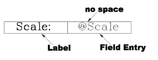
To enable Graphite to identify the title blocks, define fields in the drawing format. To define a field, create a regular text block, and type an @ character in front of the text. Any text following an @ character then becomes a field. For example, to create an entry field for Scale create a text block and type “@Scale” in the box. For a label in front of the field, create another text block without an @ character. The following illustration shows two text blocks. One is the label (a standard text block), one is the field (a text block beginning with @).
Note: All field and label text blocks have to be placed on the Forms layer. (Create this layer using the Layers command as discussed in Chapter 13.)
Preparing Title Blocks with the Forms Command
1. Open one of the drawing formats in the Layout folder.
2. If no layer with the name Forms exists, create this layer by choosing Layout>Layers and make it the current layer.
3. Select the Text command from the function palette.
4. Create text blocks. Any text block beginning with an @ character will become a field, all others will become labels.
5. Assign to all of the text blocks the desired font, style and size using the Selection tool from the tool palette.
6. Save the drawing format.
With a format already placed in the drawing, selecting the Forms command in the Forms Text submenu brings up the Forms dialog box. This dialog box is similar to the Resolve dialog box in that it prompts the user for values for each previously defined field. Graphite replaces the field text blocks with whatever values are entered. Text attributes, such as font, assigned in the saved format are applied to the new values.
1. Place a Standard drawing format (use the Import or Sheet into View command). The form appears with all of the field labels as they were originally created.
2. Choose the Text>Forms Text>Forms.
The Forms dialog box containing all entry fields of the title block displays.
3. Type in the desired parameters. All entry fields need not be filled.
4. Click OK.
The Forms dialog box closes and all entry fields of the selected title block are filled in according to your specifications.
1. Select the fields containing values to update (or choose Edit>Select All).
2. Select the Text>Forms.
The Forms dialog box displays again.
3. Modify the entries of the title block.
4. Click OK.
The Forms dialog box closes and the selected title block is modified accordingly.
Printing or Plotting a Drawing
Graphite prints and plots on most printers and plotters. Follow the manufacturer’s instructions for installing and setting up the printer or plotter, then size the drawing for the paper.
Setting the Printer or Plotter and Paper Specifications
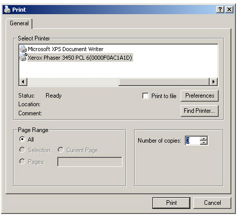
In the File menu, use the Print Setup (Windows) or Page Setup (Macintosh) to specify the printer or plotter, the paper size, orientation, number of copies and other options.
Once the page setup is specified, set the visual scale of the geometry so that it fits the paper size.
Follow the instructions found earlier in this chapter to scale the geometry visually to fit the paper specified in Print Setup (Windows) or Page Setup (Macintosh).
CTRL+P (Windows); z+P (Macintosh)
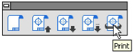
The Print command in the File menu, or the last icon in the Window>General palette, prints or plots the current document as specified in Print Setup (Windows) or Page Setup (Macintosh).
The area printed or plotted is the portion that fits on the page size specified in Print Setup (Windows) or Page Setup (Macintosh) when the origin (0,0) is placed in the center of the page. Choose Layout>Drawing Size to scale the drawing to the appropriate size and reposition the print/plot region.
Specify tiling (printing on several pages to be pasted together) through the Drawing Size command. If there is more than one sheet or tiling is specified, it is possible to designate which page(s) to print/plot. Pages are numbered sequentially for tiling, then for additional sheets.
It is also possible to plot to a file rather than to a plotter or printer. In that way, a plotter does not need to be attached to the computer. Someone else can plot the drawing without having a copy of Graphite on the plotter’s computer.
The type of plotter chosen when setting up the page determines the format of the plot file.
By choosing a PostScript printer, the file format will be Encapsulated PostScript; and the HPGL language is used when Hewlett Packard plotters are selected. The computer that finally plots the file must have an application compatible with the file format of the printer or plotter.
When you are using a plotter, specify the Plotter font for the text and dimensions on the drawing. It is also possible to specify different text styles (such as italic or bold) in the Text menu and generate special characters and accents as described in Appendix B: Special Characters.