


This chapter describes the options for adapting Graphite to your needs. The following topics are covered:
• The Grid
The pen style determines the appearance of lines on the screen and during plotting. Using a monochrome monitor or printer, all lines are black but the weight and pattern are visible. Any line thickness of less than .016 inch appears one pixel wide on the screen. When printing or plotting such lines, you will see that the different weights are observed.
The default pen style is Outline—solid, black lines, .01 inch wide. Change to a different pen style or change an individual characteristic of the current pen.
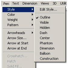
Choose from nine different pen styles in the Pen menu. The characteristics are listed below.
|
To change pens, choose among four options:
• Choose Pen>Style from the menu and select a different pen style from the list. The current pen style is checked.
• Choose a pen from the Pen Style palette accessed under Windows>Show Pen Styles Palette.
• Choose different characteristics for the current pen from the pen characteristics listed in the Pen menu (Color, Weight and Patterns).
• Use Pen>Style>Edit Style to permanently alter the characteristic of the pen.
Changing the Pen Characteristics of an Object
1. Select the object.
2. Choose Pen>Style and select the pen style to change the characteristics of the selected object. To change one characteristic rather than the entire pen style, choose the characteristic from the pen characteristics listed in the Pen menu.
When changing this, the current pen also changes, thus affecting future constructions.
To change the pen characteristics of an object without changing the current pen, select the object, then choose Edit>Edit Objects and change the characteristics in the dialog box.
The following characteristics are available from the submenus in the Pen menu.
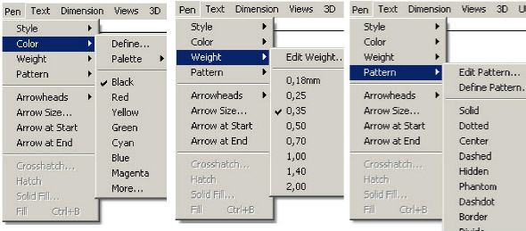
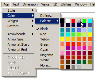
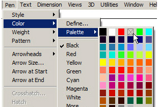
There are 234 color options including 170 user definable colors and 64 predefined colors. This Color palette displays the 64 predefined colors in Pen>Color>Palette.
Each definable color can be independently assigned from the 16.7 million colors available.
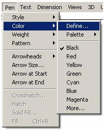
This Color command specifies the color of the current pen and any other selected geometry without changing any other pen characteristics.
Specifying the Color of the Current Pen
1. Choose Pen>Color. The submenu appears.
2. Choose the color.
The pen takes on the new color as selected in the submenu.
3. Deselect any geometry to see the chosen color.
As many as 234 colors may be defined. By choosing Layout>Preferences>Save Preferences following their definition, they are available each time a new file is opened.
Because the color displays are different for Windows and Macintosh machines, the process for defining a color vary slightly. See your Windows or Mac documentation for information on how to define custom colors on your platform.
1. To define a new color, choose Pen>Color>Define.
2. The Edit Colors dialog box appears.
3. In the dialog box window, scroll down and select one of the undefined color numbers, like <User65> (the first definable color available).
4. Enter the color name in the Color Name data field and click Rename. The name entered replaces User <65> in the colors list, as displayed here.
5. Click Define. The color display appears on the screen.
Follow the directions in your Windows or Mac operating system documentation on to create custom colors.
6. When you have finished creating any custom colors, save these colors as default color settings for all new files by choosing Layout>Preferences>Save Preferences.
Edit the previously defined colors using a procedure similar to that for defining colors.
1. Choose Pen>Color>Define.
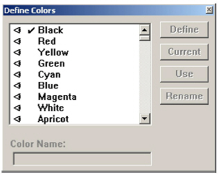
2. The Define Colors dialog box appears.
3. In the dialog box window, scroll down and select one of the defined colors.
4. Click Define. The color display appears.
Edit the color.
5. Click OK to save the changes.
Tech Note: The 64 predefined colors that came with Graphite cannot be redefined or edited.
Choose Layout>Preferences>Save Preferences to save the colors defined. Colors created for a specific file are saved with the file if they have not been saved using Save Preferences.
This feature designates which colors display in the Palette when choosing Pen>Color>Palette.
Displaying a Color in the Palette
1. Choose Pen>Color>Define.
2. Select the color to display.
3. Click Use. An eye icon appears next to the color name.
Click in the blank space to the left of the name to display the icon.
Choose Pen>Color>Palette to see that the color patch has been added to the palette.
Removing a Color from the Palette
1. Choose Pen>Color>Define.
2. Select the color to remove.
3. Click No Use. The eye icon next to the color name is removed.
Click on the eye icon to remove it.
When choosing Pen>Color>Palette, the color patch has been replaced by a patch with an X in it.
This command in the Pen menu sets the pen width of the current pen and selected lines without changing any other pen characteristics.
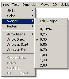
The line weights shown in this submenu depend on the units selected in the Preferences submenu. If metric units are selected, the line weight is shown in millimeters instead of inches.
Note: Any line thickness that converts of less than .016 inch in your resolution appears one pixel wide on the screen. When printing or plotting such lines, the different weights are seen.
Specifying a New Weight for the Current Pen
1. Choose Pen>Weight. The submenu appears.
2. Drag to the desired weight.
The pen takes on the new weight, as selected in the submenu.
This command from the Weight submenu in the Pen menu sets the line weights. Graphite comes with eight default line weights ranging from .002” (.05mm) to .050” (1.27mm). Objects drawn in Graphite are drawn in one of the eight available pen weights. Choose Pen>Weight>Edit Weight to change the weight of one of the pens to any value between .001” (.0254mm) to .050” (1.27mm).
There cannot be more than eight different pen weights in a drawing, so changing a pen weight in the Edit Pen Weights dialog box changes the weight of every object drawn with that pen’s previous weight.
1. Choose Pen>Weight>Edit Weight. The Edit Pen Weight dialog box appears.
2. Select the pen weight to change by clicking on the pen number. That pen’s data field is selected.
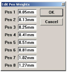
3. Change the pen weight by typing a new value into the data field. If no units are given with the entry, Graphite applies the unit specified in the Units dialog box from Preferences.
If the entry does not fall with in the valid range from 0.0001" (.00254mm) to 5" (127 mm), Graphite prompts with an Alert box similar to the one here.
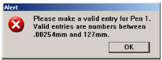
Note: While Graphite will accept any entry between these values, most printers will not print a line over 0.5" (1.27mm), nor will the screen display anything less than 1 pixel.
Clicking OK in the Alert box returns to the Edit Pen Weights dialog box to make the necessary changes.
4. Click OK in the Edit Pen Weights dialog box. All existing lines drawn in the pen weight that was edited change to reflect the new weight, as will all future lines drawn in that pen weight.
Clicking Cancel ignores all changes made to any pen weights and closes the Edit Pen Weights dialog box.
Do not undo editing a pen weight with the Undo command. To return a pen to Graphite’s default, enter the original value in the Edit Pen Weight dialog box, following the steps described above.
The default weights are: Pen 1 - .002", Pen 2 - .005", Pen 3 - .010", Pen 4 - .016", Pen 5 - .020", Pen 6 - .032", Pen 7 - .040", Pen 8 - .050".
Edited pen weights affect only the pen weights in the current file. To save the edited pen weights so that they are available in all future files, choose Layout>Preferences>Save Preferences.
Tech Note: Remember that all pen weights thinner than .015” appear on the screen as one pixel thick. It is possible to see the difference in pen weights on the prints and plots.
Graphite provides eleven standard line patterns and the ability to create nineteen additional line patterns. Using the Pattern command, set the pattern of the current pen and any selected lines without changing any other pen characteristics. Define new patterns and edit all line patterns currently available.
Specifying a New Pattern for the Current Pen
Choose a standard line pattern or a user-defined pattern. When selecting a pattern, regardless of whether an object is selected, the pattern becomes the current pen. If a particular pen style had been previously chosen, notice that style is no longer checked in the pen style submenu.
1. Choose Pen>Pattern. The submenu appears.
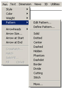
2. Select a pattern.
The pen takes on the new pattern.
Setting a User-defined Pattern
1. Choose Pen>Pattern>More. The Line fonts dialog box appears.
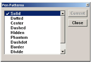
2. Scroll down to the desired pattern and select it.
3. Click Current.
The pen takes on the new pattern.
Defining and Editing Pen Patterns
Edit the standard patterns included with Graphite or create up to nineteen patterns of your own.
This command, found by choosing Pen>Pattern>Define Pattern, defines up to nineteen line patterns.
Graphite considers each line segment and each space between line segments separate dashes. Each dash has a handle, represented by a box attached to the vertical line extending from the end of each dash.
One complete element of the line pattern appears in the pattern window. The default visible length is two inches. To create patterns with dashes or elements larger than two inches, change the value in the Visible Length data field to an appropriate number. The Pattern Window scales the pattern element accordingly.
Graphite automatically scales line patterns by the inverse of the scale factor set in the Drawing Size dialog box or Sheet Into View dialog box so that the pattern spacing is appropriate for the viewing and drawing scale of the geometry. Set the pattern spacing independently of the viewing or drawing scale, or change the pattern altogether. The Edit Pattern dialog box controls the pattern spacing for nine of Graphite’s eleven different line patterns. Solid and dotted patterns cannot be edited.
These patterns are saved as default patterns by choosing Layout>Preferences>Save Preferences.To save these patterns with the file only and not as default patterns, just save the file.
1. Choose Pen>Pattern>Define Pattern. The Define patterns dialog box appears.
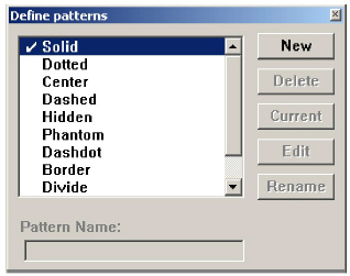
2. Click New.
The User1 default name is added to the bottom of the patterns window and appears in the Pattern Name field.
3. Click Edit. The Edit Pattern dialog box appears with the default name User1 in the Edit Pattern field.
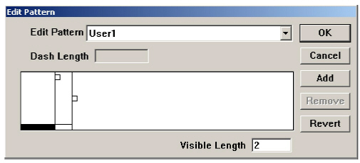
By default there are two dashes, a solid line segment and a blank segment.
4. Create the pattern by modifying the length of these segments and/or adding dashes.
Clicking the dash handle (to the right of the dash) activates the handle for the pattern segment. The dash’s current length appears in the Dash Length data field. There are two ways to change the length of a dash:
Enter a new value in the Dash Length data field and change the length of the selected dash.
Drag the handle. While dragging, the dash’s length updates in the Dash Length data field. Release the mouse button when the dash is of desired length.
To add a new dash, click Add. A blank, solid dash is added with a length of zero. The solid dash handle is activated. Change the length of the new dashes by dragging their handles or by typing in a value in the Dash Length data field. If a handle is selected before clicking Add, the new dashes are placed in front of the selected dash.
To remove a dash, select its handle and click Remove. The dash is removed from the pattern element.
Note: Pattern elements start with solid dashes, and then switch to blank dashes, and then, if necessary, back to solid, and so on. Adding or removing dashes may change existing dashes from solid to blank or from blank to solid.
5. When the pattern element is properly defined, click OK. The new pattern is created and the program returns to the Define patterns dialog box.
Click Cancel to close the Edit Pattern dialog box without retaining the pattern settings.
6. Select the Pattern Name field and enter a new name for the pattern.
7. Click Rename.
8. Click Current to set the pen to the new pattern.
9. Click the Close button in the title bar to close the dialog box.
This command, found by choosing Pen>Pattern>Edit Pattern, edits all line patterns but Solid and Dotted.
To edit a pattern already used in geometry within the drawing, the geometry automatically updates to the revised pattern. For example, if the Phantom line pattern is edited, every line in the existing document drawn in the Phantom line pattern changes to reflect the revision.
Edited line patterns also scale by the inverse of the viewing and drawing scales, but editing the pattern controls how the patterns appear on the screen and on paper.
1. Choose Pen>Pattern>Edit Pattern.
The Edit Pattern dialog box appears.
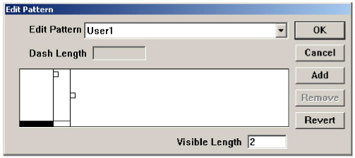
2. Select the line pattern to change from the Edit Pattern list.
3. Modify the line pattern by changing the lengths of existing dashes or by adding or removing dashes to or from the element.
4. When the pattern element is properly defined, click OK and the dialog box closes. All existing lines drawn in the edited line pattern change to reflect the new pattern element, as will all future lines drawn in the line pattern.
Click Cancel to ignore all the changes made to any pattern elements and close the Edit Pattern dialog box.
Do not undo a pattern edit with the Undo command. To return to the standard patterns that came with the program, click Revert in the Edit Pattern dialog box. Revert changes the line patterns back to their defaults, not just the pattern selected from the Edit Pattern list. A warning message is presented using Revert.
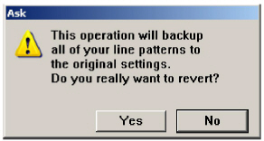
Clicking Yes changes the patterns back to Graphite’s original settings. Clicking No returns to the Edit Pattern dialog box without returning changing the current settings.
To undo changes made to user-defined patterns, previously saved as a preference, save the file (if necessary), close and relaunch the program, and then open the file. All user-defined patterns return to their previously defined settings. Edited Patterns affect only the patterns in the current file. To save the edited pattern so that it is available in all future files, choose Layout>Preferences>Save Preferences.
Pen styles help simplify the design process by defining the color, weight and pattern type for each style. Then rather than having to set each pen characteristic each time a specific type of line is desired, choose one of the predefined styles. Nine pen styles are provided.
The following are the default settings for the styles in the Pen menu:
|


Modify a pen style as needed. Change one characteristic of the style by choosing it in the Pen menu or change the style for the duration of the work session by choosing Pen>Style>Edit Style.
Changing One Characteristic of a Pen Style
1. Choose the pen to modify.
2. In the Pen menu, choose a characteristic: Color, Weight, or Pattern.
To return a standard pen to its original specifications, choose a different pen style from the menu and then choose the modified pen again. Change all of the specifications for a standard pen by redefining it with the Edit Style command by choosing Pen>Style>Edit Style.
This command from the Style submenu of the Pen menu sets the characteristics for the pen styles.
Redefining the Specification of a Pen Style
1. Choose Pen>Style>Edit Style.
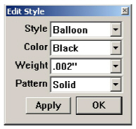
The dialog box appears.
2. Select the pen style to change by pressing the Style data field.
When the list of pen styles appears, choose the style to change.
3. Specify the characteristics (Color, Weight, and Pattern) for that style.
4. Click OK to set the specifications and close the dialog box, or click Apply to put the specifications into effect for a single pen style and leave the dialog box open to make changes to another pen style.
When editing a style, set new specifications for future uses of that pen. The specifications remain in effect for the document in which they are set until changed again with the Edit Style command. Change the default setting of any pen style by saving changes in the preferences file. See the “Saving Preferences” section at the end of this chapter.
Although style characteristics can be changed, style names cannot. Keep this in mind changing the pen pattern. Otherwise, the style name may not reflect the pattern and cause confusion if the changes are saved as a preference.
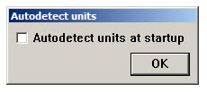
Graphite is set to measure geometry in inches. When opening a new drawing, set the precision, units, and fractional or decimal specifications as needed. Upon opening Graphite for the first time, the Autodetect Units dialog window opens. Check an Autodetect units at startup option to make the software perform units detection when a file is imported or opened.
This command is found by choosing Layout>Preferences>Units. A dialog box displays.
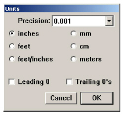
|
All geometry reflects the new unit measurement, converting automatically between English and metric. When changing the units, existing dimensions update to reflect the change.
Using the Status Line to Specify the Unit of Measure
Use the Status Line to specify a unit of measure other than the one in effect for the document. If the units are set to inches for drawing a line, use different units of measure such as inches ("), feet ('), feet and inches (x'y”), millimeters (mm), centimeters (cm) and meters (m). Mix the units in the mathematical expression if they are labeled properly. For example: 10" + 25.4 cm.
In the following example, if the units are set to inches, enter 23' in the Length data field as shown below.

When ENTER (Windows) or RETURN (Macintosh) is pressed, a line 23 feet long is drawn. Graphite converts the length to inches and the Status Line displays the length in inches because of the Units setting.
In addition, it is permissible to use mathematical, exponential, and trigonometric expressions in the Status Line. Appendix A provides examples of the valid operators.

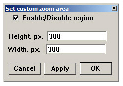
When the Grid is visible, objects snap to the grid spacing. To place an object between the grid marks, either turn off the grid, change the grid spacing, or zoom in so that the spacing is larger than the Hit Radius. The grid spacing automatically reflects the units set in the Units dialog box. When the units are changed, the appearance of the grid spacing remains the same, and the values listed in this dialog box change automatically.
This command, found in Layout>Preferences, sets the spacing of the grid lines and grid color. Specify the number of ticks (subdivisions) per unit (spacing) and the grid color as necessary. Change the default setting by saving changes in the preferences file.
CTRL+G (Windows);z+G (Macintosh)
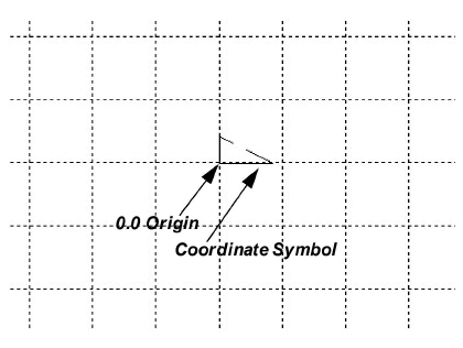
This command in the Layout menu controls the display of the grid. The grid is made up of horizontal and vertical lines of dots. The spacing of the grid lines and the number of tick marks between the intersections are set in the Grid dialog box by choosing Layout>Preferences>Grid. When the grid is visible, the Drafting Assistant snaps to the grid spacing. In other words, if the grid is set to .25 inch spacing, constructing an object cannot be done closer than .25 inch to another object.
The coordinate symbol appears at the origin location (X=0, Y=0) when the grid is visible.
Tech Note: To change the Hit Radius, choose Layout>Preferences>Snap.
Changing the Grid Spacing, Subdivision and Color
1. Choose Layout>Preferences>Grid.
The Grid dialog box displays.
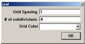
2. Enter the desired values for Grid Spacing and/or # of subdivisions.
3. Select the grid color from the drop down menu.
4. Click OK and the changes are saved.
Click Cancel to prevent saving the changes.
Whether designing or drafting a highly detailed blueprint, create the geometry at its actual size. In Graphite it is possible to construct the part using full-scale specifications and then set the visual scale of the drawing. In this way, the part dimensions to its true-to-life measurements. Drawing at full scale has the following advantages:
• Scaling mistakes are eliminated.
• Dimensions are automatic (dimension manually if drawing is not at full scale).
• Associative dimensions update when the object is edited (manual dimensions do not).
• The size relationship of imported parts is compatible.
• Calculations for 2D analysis are accurate.
Once the project is drawn, dimension it, scale it visually and size it to fit into a standard drawing format, if necessary. The actual size of the geometry remains constant unless edited.
When opening a new Graphite document, the drawing area is a sheet that is infinitely large so that anything can be designed at full size. For a simplistic example, here's how to draw and view a line 83 feet long:
1. Draw a line, specifying 83' for the length.
The line extends off the screen.
2. Choose Arrange>Zoom All.
The entire 83 foot line is visible on the screen.
Using the draw to scale/Zoom All method, create accurate full-scale drawings which are displayed at the magnification chosen. The actual size of an object is not affected by zoom magnification or reduction.
Zoom All magnifies or reduces all objects on the drawing to fill the screen regardless of the size of the objects.
The drafting process may or may not include using a standard drawing format.
Since the geometry is created at full scale, the basic difference in the two drafting processes is how the visual scale of the geometry is set so that it fits on the paper or in a drawing format. Most steps are discussed in the following two drafting procedures. They are also discussed in greater detail in later chapters.
Drafting without a Drawing Format
1. Start Graphite and display an Untitled document.
2. If necessary, set the Units of measure to use by choosing Layout>Preferences>Units.
3. Construct the geometry at full size, saving the construction while working. Use the Zoom commands and tools to display the part at an appropriate magnification in order to see what is done.
4. Choose File>Print Setup (Windows) or Page Setup (Macintosh) command to set the paper size for plotting or printing.
5. Choose Layout>Drawing Size to set the drafting scale for plotting or printing.
Specify the drafting scale for the drawing, such as 1:120 or 1":10' for 1 inch to represent 10 feet. If the scale is not of concern and the final geometry only needs to fit on the selected paper size, specify Fit to adjust the geometry automatically to the paper size.
6. Dimension the part and add text.
When specifying the visual scale for the drawing with the Drawing Size command, Graphite scales text, dimensions, hatches and line patterns inversely with the same scale factor so that all text and dimensions added after scaling have exactly the size specified in the Size submenu in the Text menu. That means if the text size is set for text and dimensions to 0.25 inches it plots at a size of 0.25 inches on the paper.
7. Make final adjustments.
8. Choose File>Print.
Drafting with a Drawing Format
1. Start Graphite and display an Untitled document.
2. If necessary, set the Units of measure by choosing Layout>Preferences>Units.
3. Construct the geometry at full size, saving the construction in the process. Use the Zoom commands and tools to display the part at an appropriate magnification in order to see what is done.
4. Use the Sheet Into View command from the Views menu to set the visual scale so that the part fits into the size of the drawing format selected in the pop-up menu in the Sheet Into View dialog box.
5. Dimension the part and add text.
When you specify the visual scale for the drawing with the Sheet Into View command, Graphite scales text, dimensions, hatches and line patterns inversely with the same scale factor so that all text and dimensions added after scaling have exactly the size specified in the Size submenu of the Text menu. That means, if the text size is set for text and dimensions to 0.25 inches, it plots at a size of 0.25 inches on the paper.
6. Make any final adjustments.
7. Choose File>Print to print or plot the drawing.
Tech Note: If text and dimensions are added before scaling the drawing with the Drawing Size command, all text and dimensions must be selected with the Selection Mask to set the text size again to the desired value, for plotting on the paper. See Scaling Text and Dimensions in Graphite Documents.
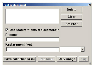
The Graphite.ini file is an ASCII text file that can be opened and edited in any text editor, including NotePad. This file contains setting for the number of fonts that appear in the Font submenu, the size of the screen when Graphite is launched, and the number of files that appear in the Recent File List.
To make changes to the Graphite.ini file, open it in any text editor and make the desired edits. Save the file as a text file. The next time Graphite is launched, it will account for the new setting in the Graphite.ini file.
This option sets the number of fonts that appear in the Font submenu from the Text and Dimension menus. Graphite takes the fonts in alphabetical order, up to the number that is specified in the Graphite.ini file. Fonts that do not show up in the menu are accessed by choosing Text>Font>Other. By default this value is left blank, so Graphite displays all the fonts.
This option sets the size of the screen when Graphite opens. There are two options. Screen=FULL opens to a maximized window. Screen=Standard opens to the standard size, which is almost maximized but with room for icons at the bottom. If no value is specified, the screen opens to the standard size.
This option determines the number of files that appear in the Recent File List from the File menu. Specify the number of files that are to appear in the File menu after Files=. The names and paths of recently opened files are saved in the list that follows the Files= line. File1= is always the most recent file opened. As new files are opened, the file list gets shifted down, so the old File1 becomes File2, and so on. The default number of files is four. The maximum number is eight.
Referral: For more information about using the Resent File List, consult the discussion of the Resent File List in Graphite Documents.
All of your system fonts are available when choosing Text>Fonts.
Specify the number of files that should appear in the Recent File List of the File menu. A file named recent.lst can be found in the Scripts folder. This file is an ASCII text file that can be opened and edited in any text editor. The following is a sample of the contents of the recent.lst file:
/aRecentFiles
4 % Number of recent files remembered (8 maximum)
store
/aRecentFileList [
(MacHD:Graphite 3D 3.0:Samples 3D:YF-22)
(MacHD:Graphite 3D 3.0:Samples 3D:Chair 3D)
(MacHD:Graphite 3D 3.0:Samples 3D:Question Mark)
()
] store
Before % Number of recent files enter a number to specify the number of files that are to appear in the File menu. The names and paths of recently opened files are saved in the list that follows the /aRecentFileList [ line. The first file in the list—YF-22 in the example above—is always the most recent file opened. As new files are opened, the file list gets shifted down. The default number of files is four. The maximum number is eight.
All files save with the settings set for the file. The characteristics used for new files (the default settings) appear in the preferences file.
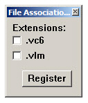
This command in the Layout menu displays a submenu for setting various specifications. Descriptions of the items in the submenu appear individually in this reference section. Change the default setting by saving changes in the preferences file, prefs.vc6 (Windows) or Graphite prefs (Macintosh).
|
Saving Preferences Information and Characteristics
The preferences filename is prefs.vc6 (Windows) or Graphite prefs (Macintosh).
To use different settings for your work, change the default settings, and then every new document opens with the settings selected. The following specifications are set in the preferences file:
• Pen styles
• Text characteristics
• Preferences settings (snap, grid, units, selection color indicator, and visualization settings)
• Grid display
• Layer and sheet specifications
• Work layer
• Dimension and tolerance formats
• Arrowhead type and display
• Drawing size and scale
• Zoom scale
• Fillet radius
• Chamfer angle and length
• Resolve values
• User defined colors
1. Create a file which has the desired preferences.
2. Choose Layout>Preferences>Save Preferences.
The preferences are set for subsequent new documents after restarting Graphite.
Be careful choosing Save Preferences when working in a file with multiple sheets, models, details views, or layers. Even though the geometry is not saved, all other data is. All new files opened subsequently will contain items that are not desired. Check the Preferences file for the items mentioned on a regular basis. The original default setting for the file includes one sheet, one model, three layers (Construction, Dimension, and Layer 1) and no detail views.
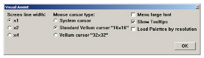
In the Preferences submenu find the Save Palettes command. When selecting this command the Status (visible/hidden) and the Location of all palettes are saved to preferences. When restarting Graphite, all palettes that were displayed while closing Graphite are automatically reopened.
Location and Status for the following palettes are saved with this command:
• Dimension palette
• Symbol palette
• Function palette
• Tool palettes
• Tear-off palettes
The Trackball does not save with this command.
For Windows, the Location and Status of these palettes are saved in the Graphite.ini file, under the section Palettes.