


This chapter describes the various advanced options that for adapting Graphite to your needs. The following topics are covered:
• Macros
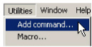
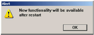
This utility adds custom functionality to the Graphite Utilities menu. Utility scripts are available in the Support Center of the Ashlar-Vellum website, can be developed by you in Ashlar-Vellum’ s FE language (similar to Postscript), or may be custom developed for you by the Ashlar-Vellum technical team. From the Utilities menu, choose Add Command and navigate to the location on your system where the script is saved. Select the file and click the Open button to place the script in the correct folder. As alert message notifies you that the new functionality will be available after restarting the software.
It is possible to create macros within Graphite and access them through menu commands, stroke commands, or key combinations, providing an alternative way to invoke these commands.
A macro automates a repetitive task by executing a group of simple commands. Define a macro by pointing and clicking.
Choose Utilities>Macro, and the following dialog box displays:
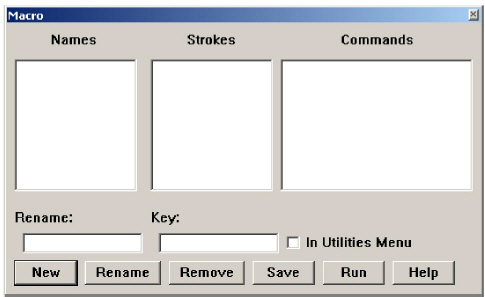
The Macro dialog box is modeless in the sense that there are no Start Recording or Stop Recording buttons. Whatever actions are performed (selecting menu items or defining strokes) are recorded automatically in the related list boxes as long as the Macro dialog box is open.
The Macro dialog box contains the following buttons:
|
1. Choose Utilities>Macro. The Macro dialog box displays.
2. Click New.
The name Macro1 displays in the Rename field.
3. Overwrite the name if desired. (Use alpha-numeric characters with no spaces.)
4. Select menu commands in the order the new macros will execute.
The selected commands are automatically filled in the Commands list box.
If a stroke command is not desired for the macro, go to step 6.
5. Define a Stroke command on the drawing area.
Press CTRL+SHIFT (Windows) or the z key (Macintosh) and drag a symbol on the drawing area to be associated with the new macro.
Use letters or a figure like a circle. Do not use Graphite’s standard stroke commands like Zoom or Construction strokes, since they are executed immediately. A letter and number combination describing the executed stroke displays in the Stroke list box automatically. When defining a stroke, repeat it several times to define all variations of the stroke, so that all possible variations are covered and can be recognized by Graphite.
6. Check the In Utilities Menu option to include the new macro in the Utilities menu.
7. Enter a Key short cut in the Key entry field.
Click in the Key data field and enter the key combination or type it directly in the Key data field.
8. Close the Macro dialog box by double-clicking the Control menu (Windows) or the Close button (Macintosh) in the upper left corner of the dialog box.
1. Display the Macro dialog box.
2. Select a macro in the Names list box.
3. Rename the macro in the Rename data field and click the Rename button.
4. Redefine the macro by executing menu items and assigning a new stroke equivalent to the macro.
5. Alter the Macro key combination in the Key data field.
6. Close the Macro dialog box by double-clicking the Control menu (Windows) or the Close box (Macintosh) in the upper left corner of the dialog box.
1. Display the Macro dialog box.
2. Select a macro in the Names list box.
3. Click Remove.
Each macro has a unique name and is run in one of four ways:
• Invoked with a key combination. Subsequent typing of that key combination causes the associated macro to run.
• Invoked by a family of stroke commands defined in the Macro dialog box.
• Selected the Utilities menu if the In Utilities Menu option was checked in the Macro dialog box.
• Executed by selecting it from the Names list in the Macro dialog box and clicking Run.
Executing a macro with the Run button is useful for testing a macro. Should it not work properly, highlight any dialog box entry and remove it by pressing the Remove button. Modify the macro as needed then test it again by pressing the Run button. Continue this process until the macro runs properly.
Macros are not general programs. There are limitations as to what is encoded in a macro. The following rules apply:
• Only menu items and tools are included in a macro.
• A menu item might cause a dialog box to appear, but the macro cannot fill in the required entries.
• There are no conditionals (like if or ifelse) or loops (like while).
• Subroutines are allowed so that one macro can call another macro, provided the called macro is in the Utilities menu and therefore a menu item. If a macro calls a nested macro which ends in an infinite loop, an alert box appears and the macro aborts.
• Macro names are limited to alpha-numeric characters with no spaces.
Graphite enables you to organize your files. The Directory command in Preferences specifies the file location for symbols and for opening, saving, importing, exporting files. See Graphite Documents for more information.
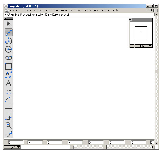
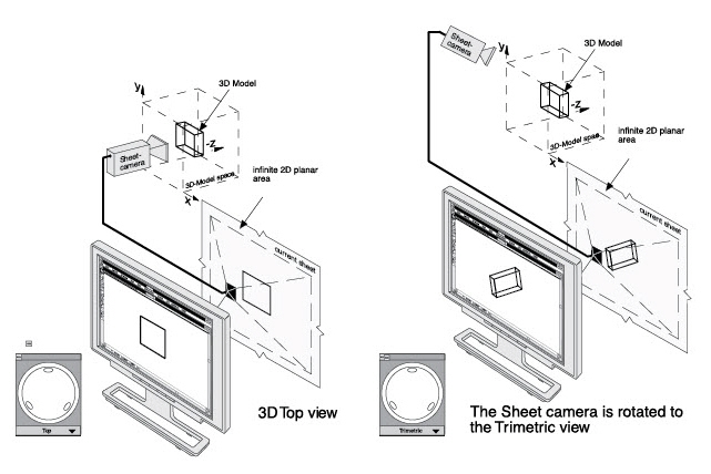
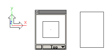
Although the transition between 2D and 3D drawing in Graphite is seamless, there are a few settings and features that are unique to 3D. When opening a new document an empty work area displays. This work area, a sheet, is an infinitely large drawing space for creating a model of any size. The new sheet displays the Top view by default on the x, y plane of the model space picked up by the sheet camera. When constructing geometry in 3D, rotate the sheet camera to a 3D view.
It is also possible to start drafting in 2D and then continue drafting in 3D simply by changing the view.
Once the sheet camera is rotated, it is as though the model rotates so that all the x-, y-, and z-directions can be seen while drawing.
There are several options for this rotation:
• Manually rotate with the on-screen Trackball.
• Select a view from the pop-up menu in the Trackball window.
• Choose a view from the Views submenu in the Views menu.
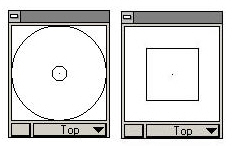
This command toggles the display of the Trackball/Trackcube window. Use the Trackball/Trackcube to rotate the view orientation in the active detail view window or the sheet view, as long as no view windows have been created. Drag the Trackball window around the screen. For more information on detail views and sheet views, see Chapter 13, “Viewing Geometry.” To rotate between the Trackball and the Trackcube, click on the box in the lower left corner.
Tip: The Trackball can be changed to the Trackcube by clicking the button in the lower left corner of the Trackball window.
Rotating the Sheet View or Active View
1. Choose Views>Show Trackball.
2. Drag the pointer on the Trackball to rotate the view.
The model rotates as you drag. The model rotates around the center of the active view or sheet.
The Trackball/Trackcube has a pull-down menu for specifying the view of the current view window or the sheet view, if there are no view windows.
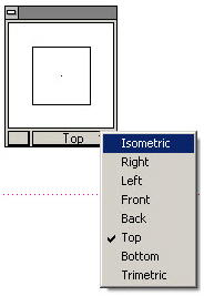
1. Move the pointer to the current view name displayed at the bottom of the Trackball/Trackcube window.
2. Press the mouse button. The Views menu displays.
3. Choose the view orientation to display in the current window.
The view orientation changes to the specification in the view window.
Tip: To see the Triad at the origin (0,0,0), set the grid spacing to 0 in the Preferences submenu in the Layout menu.

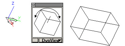
This feature locks the Trackball/Trackcube along two screen axes so that the view of the geometry is rotated around the third screen axis. The screen axes are different from the axes of the geometry unless the top view is set.
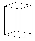
It is possible to rotate the view of this block around the x-,y- or z-axes of the geometry or the screen.
Rotate View around an Axis of the Geometry
To rotate the view around an axis of the geometry, change the view to Top, either from the Trackball menu or choosing Views>Views>Top. This makes the screen axes the same as the axes of the block.
To rotate around the x-axis, place the cursor on the Trackball, hold down the SHIFT key and drag the cursor up or down. The geometry rotates around the x-axis.
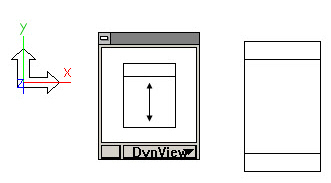
Holding down the SHIFT key locks both the y- and z-axes.
To rotate around the y-axis, place the cursor on the Trackball, hold down the CTRL key (Windows) or the OPTION key (Macintosh) and drag the cursor to the left or right. The geometry rotates around the y-axis.
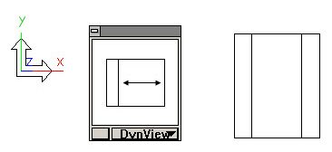
Holding down the CTRL key (Windows) or the OPTION key (Macintosh) locks both the x- and z-axes.
To rotate around the z-axis, place the cursor on the Trackball, hold down the CTRL+SHIFT keys (Windows) or the z key (Macintosh) and drag the cursor in a circular motion. The geometry rotates around the z-axis.
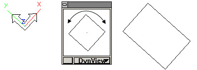
Holding down the CTRL+SHIFT keys (Windows) or the z key (Macintosh) locks both the x- and y-axes.
Rotate View around the Screen Axis
With the same block displayed in any view, simply use the key combinations listed previously to rotate around the desired axis.
If the geometry is displayed in the trimetric view and it needs to be rotated around the screen's z-axis, place the cursor on the Trackball, hold down the CTRL+SHIFT keys (Windows) or the z key (Macintosh) and drag the cursor in a circular motion. The geometry rotates around the screen's z-axis.
This command toggles the display of the Triad symbol in the upper-left corner of the view windows. The Triad illustrates the orientation of the x, y, z axis and the work plane. This symbol also temporarily displays at the origin and rotates as the view orientation is rotated manually with the Trackball.
If a detail view is not created, the Triad symbol displays in the upper-left corner of the sheet. Once a view window is created, the sheet camera cannot be rotated any more. It remains stationary at the world orientation. For more information on detail views and sheet views, see Viewing Geometry.
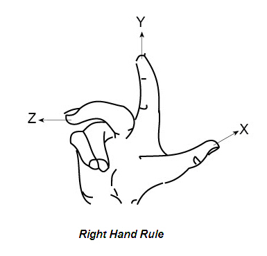
The Triad represents the principle of the right-hand rule—a memory aid for the relative directions of the positive axes. With your right palm upturned, the thumb (x) points right, the index finger (y) points straight ahead, and the middle finger (z) points up. If you move your hand to indicate the x and y-axes, you can easily see the direction of the z-axis.
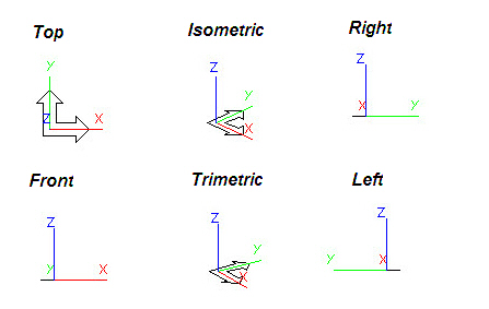
This command displays the view orientation submenu to set the orientation of the sheet view or active view window.
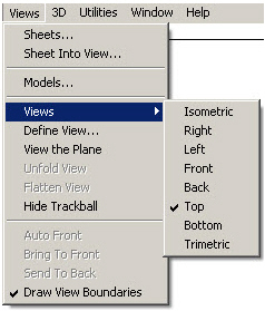
The standard views, Front, Isometric, Right, Top and Trimetric, are always displayed in this menu. Create new views with the Define View command and those views are listed in this menu. Views are also selected from the Trackball menu.
The selected view orientation affects the active area, including the sheet view or the active view window.