


This chapter describes several Graphite features for viewing geometry in the drawing in different ways. The following topics are covered:
• Layers
• View Displays and Detail Views
Graphite offers several ways to change the magnification of the drawing by zooming in and out using commands, zoom tools, and strokes.
Zoom In, Zoom Out, or Zoom All from the Arrange menu all change the view magnification of the geometry. The Zoom Previous command returns to the last magnification. To zoom on a particular area, use the Stroke feature or the Zoom In tool. Strokes are described later in this chapter.
CTRL+F (Windows); z+F (Macintosh)
The Zoom All command in the Arrange menu zooms in or out to make all objects on the drawing fill the screen, regardless of how big or small the objects are.
CTRL+] (Windows); z+] (Macintosh)
The Zoom In command in the Arrange menu zooms in on the center of the screen by a factor of two. A particular area cannot be specified for enlargement.
CTRL+[ (Windows); z+[ (Macintosh)
The Zoom Out command in the Arrange menu zooms out from the center of the screen by a factor of two. The area of reduction can not be specified.
The Zoom Previous command in the Arrange menu zooms to the previous magnification, up to five times.
Tip: Use the Zoom tools or Stroke zoom to zoom to a particular location.
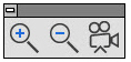
Select the appropriate zoom tool from the View Control tool palette.
With the Zoom tools, drag a box around an area on the screen, so only that area magnifies on the screen.
1. Select a Zoom tool from the tool palette.
2. With the mouse button pressed, drag a box around an area on the screen to magnify or reduce.
3. Release the mouse button.
The content of the dragged box is made visible on the screen.

The Zoom In tool, zooms in by the specified factor. The default factor is two. This is a visual rather than a physical change.
Click in the drawing area and that position redisplays in the center of the screen with the drawing enlarged by a factor of two.
It is also possible to drag a box around an area, so only that area magnifies.

The Status Line shows the current zoom scale. Enter a different scale and press ENTER (Windows) or RETURN (Macintosh) for the new scale to take effect.
Pressing the CTRL (Windows) or the OPTION (Macintosh) key while using this tool causes it to change to the Zoom Out tool.
Tip: Toggle between Zoom In and Zoom Out using the CTRL (Windows) or the OPTION (Macintosh) key.

The Zoom Out tool zooms out by the specified factor. The default factor is one half. This is a visual rather than a physical change.
Click in the drawing area and that position displays in the center of the screen with the drawing reduced by one half.

The Status Line shows the current zoom scale. Enter a different scale and press ENTER (Windows) or RETURN (Macintosh) for the new scale to take effect.
Pressing the CTRL (Windows) or the OPTION (Macintosh) key while using this tool causes it to change to the Zoom In tool.
The Detail View tool is discussed further in this chapter under View Displays.
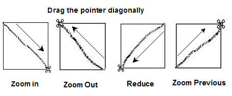
Use stroke commands to zoom in or out on the drawing. Stroke commands are useful because they don’t require getting out of the current tool in order to zoom. Hold down the SHIFT+CTRL keys (Windows) or the z key (Macintosh) and drag the pointer diagonally across the screen as described below. The pointer takes on the z shape when holding down the SHIFT+CTRL (Windows) or the z key (Macintosh) keys.
|
Note: For Zoom In and Zoom Out, the size and location of the stroke rectangle is important for determining the result of the Zoom operation. For Zoom Previous, the size and location of the stroke rectangle is irrelevant. All cases just give the previous magnification.
The mouse scroll wheel zooms in and out of a Graphite drawing using the cursor as the anchor point.
Using the Mouse Scroll Wheel to Zoom
To zoom in:
1. Place the cursor at the desired area to anchor the zoom.
2. Scroll the mouse button backwards.
The drawing zooms closer keeping the cursor in the same position.
To zoom out:
1. Place the cursor at the desired anchor point.
2. Scroll the mouse wheel forwards.
The drawing zooms out keeping the cursor in the same position.
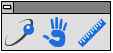
The Orbit tool rotates the sheet camera around the 3D model. The 3D objects are fixed even if it gives the impression that they are moving. The Pan tool moves the sheet camera in the x and y directions. Panning past the document edges automatically scrolls the view in that direction. The Measuring tool displays the distance between two points.
1. Select the Orbit tool from the tool palette.
2. Drag across the screen in the desired direction to move around the geometry.
The camera moves in increments of about 90 degrees with each stroke.
1. Select the Pan tool from the tool palette.
2. Drag across the geometry in the desired direction.
3. Hold the cursor at the edge of the window for the geometry to continue scrolling in that direction.
4. Hold the cursor on the edge of the opposite window to move it back.
1. Select the measuring tool from the tool palette.
2. Click the first point from which to begin the measure.
3. Click the end point.
The distance displays in the status box at the bottom of the screen.

Use the spacebar to activate the dynamic pan tool while within any operation except text.
1. Place the cursor over the portion of the drawing to move.
2. Hold down the spacebar. The cursor changes to the hand.
3. Move the cursor in the drawing area in any direction.
The drawing dynamically moves at the same zoom level.
Layers are like pages, some transparent and some invisible. Use layers to show and hide various components of the drawing. They are particularly useful in helping to view and plot complex drawings. For example, when dimensioning a part, the dimensions can be placed on a separate layer which can be displayed or not, as required. Layers allow plotting different versions of the same document for quick and easy specialized blueprints. Some examples of their usefulness:
• Hide the dimension layer to exhibit the idea of a design to a planning team and show the dimensions when presenting the drawing to engineers.
• Hide some drawing components when printing or plotting. For example, hide the construction layer so that construction lines and geometry don’t print or plot, but they remain in the drawing ready for use with design revisions. Think of visible layers as transparent pages and hidden layers as invisible pages. Although objects on hidden layers cannot be seen, they do exist. The layer must be visible for objects on it to be selected. Nor can those objects be deleted using Select All unless the layer is visible.
• Construct different layouts using one layer as the basis. For example, use a floor plan and then construct the electrical and plumbing plans on different layers. Then, turn off one layer (the electrical plan, for instance) and print the other (the plumbing plan) with the floor plan.
• Drag the layer to the desired order in the layers list and drop.
Graphite provides up to 255 visible or hidden layers in the drawing.
Many CAD drawings show different components in different colors. When specifying a different color for a layer, the layer remembers the color so that if geometry is added to a layer later, the new geometry appears in the same color as the last geometry constructed on that layer. In this way, the Visible pen in red can be used on one layer, green on another layer and so on.
1. Choose Layout>Layers.
2. Create a new layer and rename it Outline green, indicating that the pen style Outline with a green color will be used on this layer.
3. Make the layer, Outline green, current.
4. Select Pen>Style>Outline.
5. Change the pen color from Black to Green by selecting Pen>Color>Green.
6. Draw a circle. The circle is created with the green color.
7. Select the Single Line tool.
8. Make Layer 1 current.
9. Draw a line. The line is created in black (the default color for the Outline pen style).
10. Select the Rectangle tool.
11. Make the layer, Outline green, current and draw a rectangle.
The rectangle is created in green.
Tip: Layers facilitate color specific wiring diagrams or electrical and plumbing blueprints.
• Layers can be saved as Preferences with specified colors.
• Layers do not have an orientation or origin in Graphite.
CTRL+L (Windows); z+L (Macintosh)
The Layers command in the Layout menu creates, deletes, hides, shows and renames layers, as well as sets layer specifications. The work layer is the active layer, the layer on which the current construction is created.
It is not possible to hide or delete a layer that is the current (active) work layer.
It is possible to change the position of any layer in the list by drag and drop.
The visible layers are indicated in the list box by an Eye icon, while a check mark indicates the work layer.
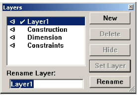
When opening a new drawing, the default layers include Construction, Dimension and Layer 1.
|
Edit any geometry or text that is visible, regardless of its layer. To make some geometry unselectable but still visible, use the Selection Mask. The selectability of entire layers can also be specified with the Selection Mask.
1. Click New in the Layer dialog box to create another layer.
2. Name the layer by typing the name in the Rename Layer data field.
3. Click Rename.
There can be as many as 255 layers.
Tip: It is also possible to type a name, then click New.
1. Select the name of the layer from the list box.
2. Type the new name.
3. Click Rename.
1. Select the name of the layer to delete from the list box.
2. Click Delete.
The layer and everything on that layer is deleted;
Note: It is not possible to delete the current work layer.
1. Click the layer(s) in the list to be hidden.
2. Click Hide. The Eye icon beside the layer name disappears.
• The current work layer cannot be hidden.
• If a layer is hidden then choosing Select All and deleting, the objects on the hidden layer are not deleted.
1. Click the layer(s) to make visible in the list.
2. Click Show.
An Eye icon appears next to the layer’s name in the list indicating the layers are visible.
Making a Layer the Current Work Layer in the Layers Dialog Box
1. Select the layer name from the list.
2. Click Set Layer.
The layer must be visible before making it the work layer.
1. Click the layer you want to relocate.
2. Drag it to a new position and drop it.
Changing the Work Layer with the Work Layer Indicator Box
Use the Work Layer Indicator pop-up box at the lower left of the drawing area to specify a different layer as the work layer.
1. Press the mouse button on the box and the menu displays.
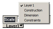
2. Drag to the layer to make it the work layer and release the mouse button.
The layer selected is now the work layer.
Determining How Many Objects are on a Layer
1. Choose Edit>Selection Mask.
2. Select the desired layer from those listed in the center box.
3. Choose Edit>Select All.
4. Choose Edit>Edit Objects. The number of objects is listed at the top of the Edit Objects dialog box.
5. Close the Selection Mask and Edit Objects dialog boxes.
Tech Note: Select a contiguous group of items in the Selection Mask by clicking on the first or last item in the desired group, then holding down the SHIFT key and either clicking on the items or dragging up or down to the other end of the desired list.
To select or deselect noncontiguous items, hold down the CTRL (Windows) or the z (Macintosh) key and click the items.
Layers are like transparent sheets that can be turned on and off. This feature is particularly useful for designs with several variations of a component or to reveal as much or as little detail as needed for the design. Here are two such uses.
A common use of layers is for different floor, plumbing and wiring plans for a building. The following examples show simplified drawings using layers.
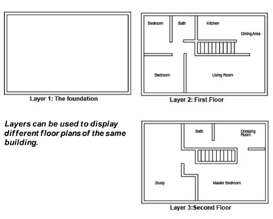
In order to print or plot the layers, simply use the Layers dialog box to turn on the layers to print and turn off all other layers using the Hide or Show button. When the desired geometry is displayed on the screen, choose File>Print.
In these examples it is also possible to observe how smart walls function. The interior walls on Layers 2 and 3 overlay the exterior walls of the foundation.
Smart walls merge only on the same layer; therefore, the interior walls are not merged with the exterior walls and walls on Layer 2 are not merged with walls on Layer 3.
Layers can also be used to create interlocking parts of an assembly. Create one part on Layer 1 and copy the common geometry onto Layer 2. Then create the remainder of the interlocking part on Layer 2.
Then, turn the display of the layers on and off to present the parts appropriately.
Layer Groups are particularly useful for viewing and plotting different layers of a complex drawing. For example, the document described in the Layers section that shows the floor plan of a house might have several layers illustrating the plumbing layout and several layers illustrating the electrical plan. The plumbing layers can be shown in the Plumbing Layer Group but hidden in the Electrical Layer Group. Similarly, the electrical layers are shown in the Electrical Layer Group but hidden in the Plumbing Layer group. To create a print to go to the electrical contractor, simply make the Electrical Layer Group be the work group. This will show the layout of the house with the electrical plan contained on various electrical layers but not the plumbing information which is on the hidden plumbing layers. Rather than having to Show or Hide numerous individual layers, you only have to select a single Layer Group to get the format that is desired.
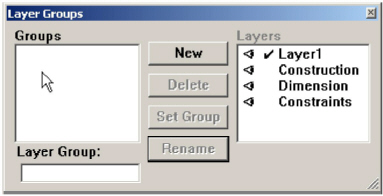
The Layer Groups command in the Layout menu extends the functionality of layers by creating Layer Groups. A Layer Group records, stores and displays layer settings, such as which layers are shown and which layers are hidden, as well as which layer is the work layer. This shows and hides different layers quickly by selecting a single Layer Group rather than setting the attributes of numerous individual layers.
The Layer Groups dialog box lists the layer groups on the left and the individual layers on the right. Visible layers for the selected (highlighted) Layer Group are indicated in the Layer list by the Eye icon, just as they are in the Layers dialog box. Visibility can be toggled by clicking the Eye icon, or at the location where the Eye icon should be for hidden layers. The work layer of the selected group is set by double-clicking on the desired layer from the Layer list. Layers that are created after a Layer Group has been defined are included in the group but are not visible.
The current set of visible layers and the work layer need not correspond to any layer group; thus, it is not necessary that a Layer Group be designated as the “work” group. Setting a work group simply changes the model’s current layer settings to those of the specified Layer Group. Also, if a Layer Group is designated the work group and layer attributes are subsequently modified, either by the Layer dialog box or by changing the work layer in the Layer Indicator pull-down list, the Layer Group loses its “work” status.
There must be at least one Layer Group created before using any of the buttons other than New, or changing any settings for any layers.
|
A check mark by a Layer Group indicates that the model’s current layer settings match those of the indicated Layer Group.
1. Click New.
A new Layer Group appears in the group list and is selected. It records the current layer settings and displays these settings in the Layers list.
The Layers list contains all the layers present in a file.
2. Choose the layer settings.
Visible layers are indicated by the Eye icon and are hidden by clicking on the symbol. Hidden layers are made visible by clicking the location where the Eye symbol would be. The work layer is indicated by the check mark and is set by double-clicking on the desired layer.
3. Close the dialog box and the settings are retained.
To have more layer groups, repeat steps #1 and #2 before closing the dialog box.
1. Select the desired Layer Group from the group list.
2. Enter a new name in the Layer Group data field.
3. Click Rename.
1. Select the desired Layer Group from the group list.
2. Click Delete.
Deleting the work group, which is indicated by a check mark, deletes the group from the list, but the layer settings remain in effect until they are changed.
Making a Layer Group the Work Group
1. Select the desired Layer Group from the group list.
2. Click Set Group. This changes the layer settings for the current model to those specified by the layer group. These settings are shown in the layers list.
A check mark by a Layer Group indicates that the model’s current layer settings match those of the indicated Layer Group.
Changing the Layer Setting of a Layer Group
1. Select the desired Layer Group from the group list.
2. Change the layer settings as desired. Visible layers are indicated by the Eye icon and are hidden by clicking on the symbol. Hidden layers are displayed in the layer group by clicking in the location where the Eye icon should be. The work layer is indicated by the check mark and is set by double-clicking on the desired layer. The new settings automatically replace the old settings.
All Models and Sheets share the same set of layers in a file. For more information about Models and Sheets, see Advanced Viewing Techniques.
View Displays and Detail Views
This section explains various ways to enlarge or reduce all or part of the geometry for both viewing and printing. This visual change of the view does not affect the actual measurement of the geometry in the model. This is different from the view orientation of the geometry that is set using the Trackball or the View commands in the Views menu. See Advanced Environment Settings. There are two types of views in Graphite: the sheet view and the detail view.
The sheet view shows all of the geometric construction on the sheet outside of any existing view windows, at the scale specified. The sheet view is the default view when starting Graphite.
The sheet view is picked up by the Sheet Camera and projected on the current sheet. The sheet view is infinite in size, having no boundaries. In other words, when drawing on a sheet, create geometry as large as desired.
Note: When selecting File>New, Sheet 1 of the untitled file is displayed. It is the only sheet available until more are added. See Advanced Viewing Techniques for more information about sheets and the Sheet Camera.
Referral: More about sheets and views is in the Advanced Viewing Techniques in this manual.
In drafting, detail views are used to provide more information about a specific area of the drawing. They are typically shown at a larger scale than the original geometry. Graphite provides a tool that automatically creates detail views in order not to have to redraw the geometry.
A detail view is like a window which looks at some geometry in the drawing from a particular camera angle and displays it at a specified scale. A detail view can be created in Graphite in two different ways: with the Detail View tool or the Sheet Into View command in the Views menu. The Sheet Into View command is an automated way of creating arrangements of detail views in specific layouts. The detail views in each case behave in the same way.
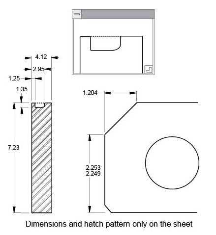
Detail views are always placed in a view window and are associative so that when modifying geometry in any view, all views of that geometry reflect the change. There are three deliberate exceptions to this associativity, in line with standard drafting practice: dimensions, crosshatching, and text appear only in the view in which they were created.
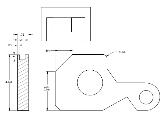
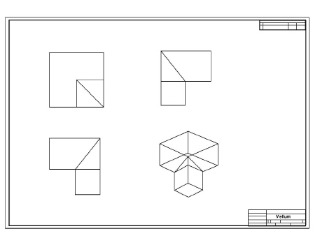
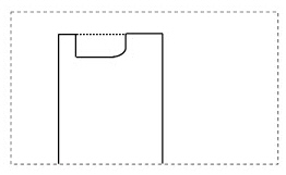
Graphite can create detail views of the drawing in which some part of the geometry is scaled and placed in a view window. In the illustration here, the detail view shows a 2 : 1 enlargement of the side notch.
Referral: See the next section for information on associativity.
Use more than one view window with different view orientations to show the various faces of the geometry. Detail view windows are useful for observing the geometry while working. They are also essential for creating finished drawings. The following graphic displays another model in four different detail views.
The Detail View tool creates a detail of the designated area of the drawing.
Creating an Associative Detail View
An associative detail view is one in which a change will appear in the view if a change is made to geometry in another view.
1. In the View Control subpalette, select the Detail View tool. The Message Line reads, Detail View: Enter view scale then pick first corner of viewing frame.
2. Enter a scale for the detail view in the Status Line.

3. Use the pointer to drag a rectangle around the area of the drawing that is to be placed in the detail view. This rectangle becomes the window frame.
It is also possible to click the first corner and the opposite corner to define the view.
4. Position the pointer in the center of the detail view window frame and drag the window to a clear area on the drawing.
5. Open the Layers window from the Layout menu and show/hide any layers for the active detail view.
Tip: It is also possible to create the view window rectangle by clicking to place the diagonally-opposite corners.
Creating a Non-associative Detail View
To have a detail view that is not associative; that is, when making changes to the original geometry, the geometry in the view does not change:
1. Create a detail view on an open space.
2. Use the Selection tool to click inside the view and make it active.
3. Drag a selection fence around all of the geometry inside the original view.
The geometry inside the view is selected.
4. Choose Edit>Copy.
5. Choose Views>Models.
6. Click New to create a new model (by default, model 2).
7. Click Current to make the new model the current model in the new view. The geometry in the view disappears.
8. Choose Edit>Paste.
The geometry is pasted into the new detail view, but it is no longer associative, since it is part of a different model.
Referral: Find more about Models and Views in the Advanced Viewing Techniques
Rotating the Viewing Area and Detail Views
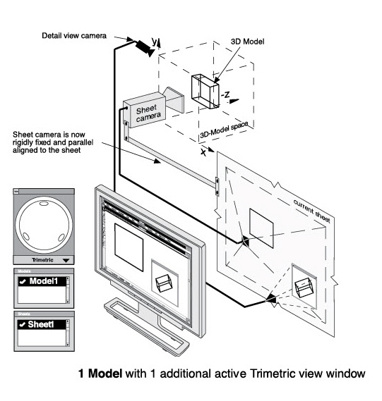
It is only possible to change the view orientation within a view window. The sheet view is rigidly fixed to the sheet itself and aligned parallel to the sheet in the Top view.
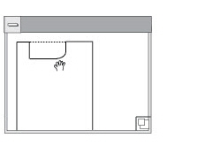
The detail view window displays a title bar only when it is the current or active view.
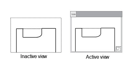
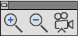
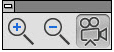
Click inside the detail view window when the view is inactive, as in the left graphic here. The detail view window becomes active, displaying a title bar and control button for its pull-down menu, as in the right graphic.
Tech Note: When clicking the detail view, the view becomes active and the view window with a title bar appears.
The sheet view is made active by clicking in the drawing area away from all detail views. In other words, all the detail views look inactive. Activate the sheet to construct geometry that is outside of a view.
A view must be active to work in it. Either a detail view is active or the sheet view is active, but only one can be active at a time.
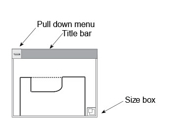
The view window includes a title bar, size box and Control pull-down menu only when the detail view is active.
Drag the view around by the title bar and resize the window by dragging the size box.
Tech Note: In the Graphite View window, the Control Menu in the upper left corner does not contain the standard control commands but special view window commands.
The Control pull down menu provides options for manipulating the view.
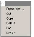
Tech Note: Using Cut or Copy within the Detail View does not cut or copy the geometry inside, but rather cuts or copies the detail view itself. To cut or copy just the geometry, use these commands from the Edit menu.
|
Tech Note: Using Cut or Copy within the Detail View does not cut or copy the geometry inside, but rather cuts or copies the detail view itself. To cut or copy just the geometry, use these commands from the Edit menu.
When fitting a view or group of views in a drawing format, it may be necessary to scale a view.
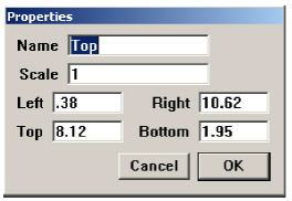
1. In the detail view's Control menu, choose Properties.
2. Specify the scale and click OK.
Tip: Scroll within a view by holding down the SHIFT (Windows) or the CONTROL (Macintosh) key while moving the scrollbars.
Use the view window menu to make another view window to add to or change the arrangement selected with Sheet Into View.
1. Click inside the window to make it active.
2. Choose Copy from the view window control menu.
3. Choose Edit>Paste.
The copy of the window appears slightly offset from the original window. Drag it to a new location.
Panning the Geometry in a View Window
1. Click inside the window to make it active.
2. Choose Pan from the view window menu.
The pointer changes to a hand icon.
3. Drag the geometry to the desired location.
1. Click inside the view to make it active.
2. Hold down the SHIFT (Windows) or the CONTROL (Macintosh) key.
3. Choose Arrange>Zoom (In, Out, Previous, or All)
or
Choose one of the Zoom tools in the tool palette.
The geometry inside the view is zoomed.
All commands from the Arrange menu work inside the view when holding down the SHIFT (Windows) or the CONTROL (Macintosh) key while choosing from the menu.
The keyboard Zoom commands are not designed to work within a view window.
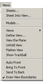
The view control commands in the Views menu control the active view. When there are overlapping views, think of them as a stack where only the top view is active. If the Auto Front command is turned on, clicking a view moves it to the top of the stack for work. This may cause some problems when an object is clicked on in the top view to select it, but an underlying view activates instead.
To remedy this situation, turn off the Auto Front command. Select the view to work in and choose Views>Bring To Front. The objects in the view brought to the front remain on top, even when clicking a different view visible in the top view’s space.
The Auto Front command in the Views menu overrides the Bring To Front or Send To Back settings. When this setting is in effect, simply click on a view to bring it to the front and make it active. When this setting is not active, it is not possible to inadvertently bring a view to the front when working on another view. This command only works for views.
This command in the Views menu brings the specified view to the front of the stack of views.
1. Select the view.
2. Choose Views>Bring To Front.
This command counteracts the Auto Front command, so a click selects objects in the view rather than activating another view.
This command in the Views menu sends the specified view to the back of the stack of views.
1. Select the view.
2. Choose Views>Send To Back.
This counteracts the Auto Front command, so a click activates another view rather than selecting objects.
This command in the Views menu shows the boundaries of all inactive views. This boundary is printed if left displayed while choosing the Print command.
To print the view without boundaries, in the Views menu, deactivate Draw View Boundaries.
This submenu on the Views menu shows the names of all the open Graphite documents. To bring a different document to the top window, choose it from the submenu.
 The Navigator Palette easily moves through sheets and layers in a circular file fashion. It displays the active documents and isolated layers.
To display the Navigator palette, choose Utilities>Show Navigator.
Click on the S>  button to move forward through the visible sheets. Click on the S<
  button to move backward. Only one sheet at a time can be shown.
Click on the L>  button to move forward through the visible layers. Click on the L<
  button to move backwards.
Click on the L+  to show all layers. Clicking L^
  pops up a list of available layers. Choosing one of the layers makes it the active layer and all other layers are visibly turned off. Restore full visibility to all layers by clicking on the
  L+ button or choosing Layout>Layers and setting the visibility individually.
Click on the W  button to display a popup menu of open Graphite documents. Choosing one of the documents makes it the active document.