


This chapter explains how to use the Dimension tools in Graphite. The topics covered include:
Graphite’s geometric dimensions are associative. This means that when a change is made to the geometry, the dimension changes also. This is not true if a manual dimension was entered in order to use parametrics, such as a value for the # in the dimension text data field).
This associativity is a tremendous time saver because dimensions automatically update whenever a change in the geometry is made. Change the units from English to metric, using the Preferences submenu in the Layout menu, and every dimension on the drawing reflects the change.
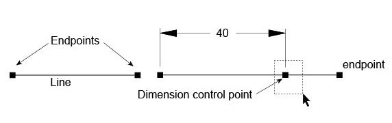
When extending a line by selecting the endpoint of the line and dragging it to a new position, the dimension changes also, because the dimension has a control point at the same position of the line endpoint. So when selecting the endpoint of the line is selected, the dimension control point must be selected also.
Dimensions are associative relative to the points they measure. When changing the length of a line using the Edit Objects dialog box, the dimension will not update because the point was not changed. To correct the dimension, select the dimension’s vertex point and drag it to the new endpoint of the line.
Graphite’s individual Dimensioning tools are in the main tool bar of the main Graphite palette.
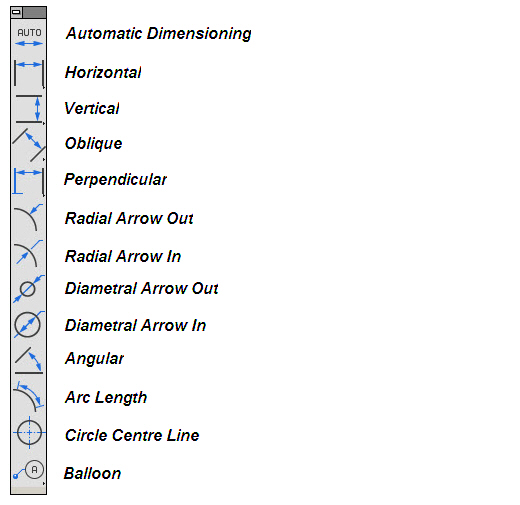
These tools are used to measure either an object or the area between objects. Once an object (or space) is dimensioned, the dimensions update when the changes are made to the geometry.
Like all palettes in Graphite, the Dimension palette can be torn off and positioned anywhere in the drawing area by clicking on the tear-off icon at the end of the fly-out palette and moving it as desired. Change the orientation of the palette by choosing either Vertical or Horizontal option in Layout>Preferences>Dimensions Palette Orientation.
Four tools on the Dimension palette have subpalettes for base line, chain, and ordinate style dimensions. To access these subpalettes it is necessary to tear off the Dimensions palette
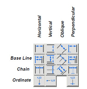
.
Some of the Dimensioning tools, such as the Horizontal and Vertical tools, require that two points be selected. Others, such as the Radial and Diametral, require only one point.
Save the location and the status (on/off) of the Dimension palette by choosing Layout>Preferences>Save Palettes.
The Dimension menu contains commands for setting the format and tolerance limits for dimensions. These commands are discussed in detail further on in this chapter under Dimension Appearance.
Dimensioning and the Work Plane
Dimensions appear in the current work plane of the active view. Set the work plane to correspond to the view before adding text or dimensions in a view.
For example, if the current work plane is the top plane, then the dimensions will appear parallel to the work plane regardless of the view. See the graphic on the next page.
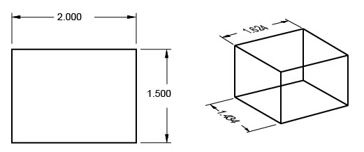
All point to point dimensions are also placed parallel to the work plane. Working in the front plane and using the Horizontal Dimension tool, the dimension is placed parallel to the front plane.
Dimensioning Objects and Placement
1. If necessary, display the Dimension palette.
2. Select the appropriate dimension tool.
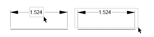
The dimension pointer is a smart pointer with a hot spot. The dot shows which side of the object to select first. Select as indicated by the position of the dot for the text to appear above or to the right of the leader. If selected in the opposite order, the text appears below or to the left of the leader.
3. Click the points to measure.
Dimensions automatically use the dimension pen style and current dimension text characteristics. To change the dimension pen color or weight, use the Dimension menu. The dimension pattern is changed in the Edit Object dialog box for dimensions that are selected.
4. Move the dimension to a new location as desired.
5. When using the dimension with parametrics, change the entry in the text data field on the Status Line.
Tech Note: Steps #4 and #5 must be done in order. If the entry in the text box is changed and then ENTER (Windows) or RETURN (Macintosh) is pressed, the dimension cannot be moved, because it is no longer selected. To move a dimension, select it and drag it to the desired location.
When the dimension text appears, it is selected so that it can be moved to a new location. Move the pointer to the dimension text. When the pointer changes to the 4-way Move symbol (the picture bellow), drag the dimension to its new location.

To move a dimension later, use the Selection tool. Click the dimension once, then drag it to the new location.
Also drag to select the dimension text or to select the entire dimension or several dimensions at once.
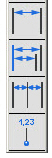
Using the Dimension Status Line Fields
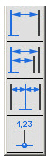
The status fields shown below appear when a dimensioning tool is selected.

|
Dimension can be edited at any time with the any of the following options:
• Click the dimension with the Selection tool and modify the Text field of the Status Line.
• Double click the dimension with the Selection tool to open the Edit Objects dialogue window and modify the Text field of the Edit Object window.
Automatically Placing Dimensions on a Separate Layer
Graphite automatically creates a dimension layer unless it is removed from the prefs.vc6 (Windows) or the Graphite prefs (Macintosh) file. To create a dimension layer, do the following:
1. Create a layer named Dimension. (This name must be spelled correctly.) The dimension layer does not need to be the work layer.
2. Dimension as usual. Subsequent dimensions automatically go on the dimension layer rather than the work layer.
1. From the Dimension menu, choose the desired style, either Linear or Angular.
2. Create the dimension.
3. Enter the values in the Status Line for upper and lower tolerance limits and press ENTER (Windows) or RETURN (Macintosh).
Delete the # symbol in the text data field (on the Status Line for a newly-created dimension or in the Edit Objects dialog box) and replace it with other text. The entry in the text data field is now fixed. It does not update if the units or the size of the geometry is changed.
Adding Special Symbols to Dimension Text
It is possible to add special symbols to the dimension text. To add a special symbol:
1. Select the desired dimension.
2. Open the Edit Objects dialog box. Next to the Text entry field there is  button. Click the button and a drop down list of symbols appears. Choose the necessary symbol.
3. Click ENTER. The symbol appears in the dimension text.
After the dimension is created, it can be exploded any time by right clicking (Windows) or Control clicking (Macintosh) and choosing the Explode option from the context menu.
The text of the dimension becomes editable within the dotted text box. Each part of the exploded dimension can be edited separately as well.
Auto Dimensioning is a convenient way to add dimensions to drawings quickly and easily. If more control over the dimension is desired, such as the style or tolerances, use the individual dimensioning tools.
This tool automatically dimensions lines (independently from their angle), circles, ellipses and arcs.
Using the Automatic Dimensioning Tool.
1. Choose the Automatic Dimensioning tool. The Message Line reads, Automatic Dimensioning: Select object for Auto dimensioning.
2. Click at each object with the Automatic Dimensioning tool.
All lines are dimensioned correctly. All circles, arcs and ellipses are dimensioned with a radial dimension.
These tools measure horizontal spaces or the distance between linear objects. To access this subpalette, tear off the Dimension palette from the main tool bar.
This tool dimensions an object or space horizontally.
Using the Horizontal Dimension Tool
1. Select the Horizontal Dimension tool. The Message Line reads, Horizontal: Pick first dimension point. The Message Line guides each successive step.
2. Click the left point of the geometry.
3. Click the right point.
The dimension appears. Drag it to a new location. Dimension and extension lines automatically redraw.
Click the points in the opposite order to display the dimension below the objects.
When the dimension text appears, drag it to a new location. Release the mouse button and the dimension and extension lines are redrawn.
Horizontal Base Line Dimension Tool
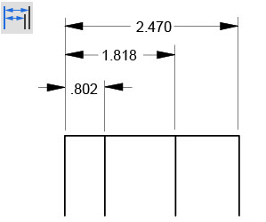
This tool dimensions objects or spaces horizontally from a base point.
Using the Horizontal Base Line Dimension Tool
1. Select the Horizontal Base Line Dimension tool. The Message Line reads, Horizontal Base Line: Pick first dimension point. The Message Line guides each successive step.
2. Click the base point of the geometry.
3. Click the point. The dimension appears.
4. Click the next place for the dimension. This dimension appears above the first, measured from the base point. Continue clicking the points to be dimensioned. Drag each dimension to a new location. Dimension and extension lines automatically redraw.
Click the points in the opposite order to display the dimension below the objects.
Tip: To access the subpalette, tear off the Dimension palette from the main tool bar.
Horizontal Chain Dimension Tool
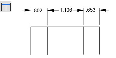
This tool dimensions objects or spaces from end-to-end, horizontally.
Using the Horizontal Chain Dimension Tool
1. Select the Horizontal Chain Dimension tool. The Message Line reads, Horizontal Chain: Pick first dimension point. The Message Line guides each successive step.
2. Click the first point on the geometry.
3. Click the second point. The dimension appears.
4. Click the next place for the dimension. This dimension appears, measured from the last point clicked. Continue clicking all the points to be dimensioned. Drag each dimension to a new location. Dimension and extension lines automatically redraw.
Click the points in the opposite order to display the dimension below the objects.
Horizontal Ordinate Dimension Tool
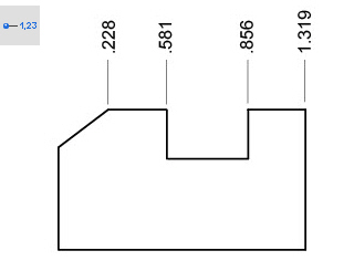
This tool dimensions objects or spaces horizontally from a base point.
Using the Horizontal Ordinate Dimension Tool
1. Select the Horizontal Ordinate Dimension tool. The Message Line reads, Horizontal Ordinate: Pick first dimension point. The Message Line guides each successive step.
2. Click the base point of the geometry.
3. Click the second point. The dimension appears, measured from the base point.
4. Click the next point for the dimension. This dimension appears measured from the base point. Continue clicking all the points to be dimensioned. To display a dimension at the base point, click the base point after having dimensioned all other points.
Drag each dimension to a new location. Dimension and extension lines automatically redraw.
Reminder: To display the dimension number of the base point, click it at both the first and the last dimension points.
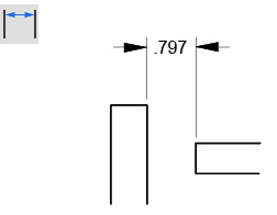
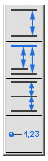
These tools measure vertical space or the distance between vertical objects. To access this subpalette, tear off the Dimension palette from the main tool bar.
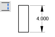
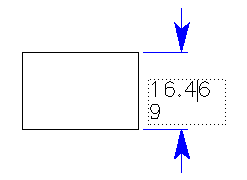
This tool dimensions an object or space vertically. Click the top point first, then click the bottom.
Using the Vertical Dimension Tool
1. Select the Vertical Dimension tool. The Message Line reads, Vertical: Pick first dimension point. The Message Line guides each successive step.
2. Click the top point of the geometry first.
3. Click the bottom point.
The dimension appears. Drag it to a new location. Dimension and extension lines automatically redraw.
Click the points in the opposite order to display the dimension on the other side of the objects.
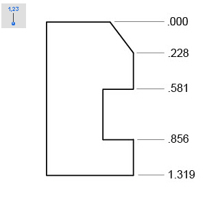
Vertical Base Line Dimension Tool
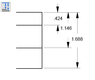
This tool dimensions objects or space vertically from a base point.
Using the Vertical Base Line Dimension Tool
1. Select the Vertical Base Line Dimension tool. The Message Line reads, Vertical Base Line: Pick first dimension point. The Message Line guides each successive step.
2. Click the base point of the geometry.
3. Click the second point. The dimension appears.
4. Click the next place for the dimension. This dimension appears to the right of the first, measured from the base point. Continue clicking all the points to be dimensioned. Drag each dimension to a new location. Dimension and extension lines automatically redraw.
Click the points in the opposite order to display the dimension on the other side of the objects.
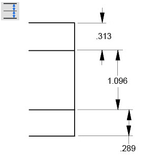
This tool dimensions objects or space from end-to-end, vertically.
Tip: To access the subpalette, tear off the Dimension palette from the main tool bar.
Using Vertical Chain Dimension Tool
1. Select the Vertical Chain Dimension tool. The Message Line reads, Vertical Chain: Pick first dimension point. The Message Line guides each successive step.
2. Click the first point on the geometry.
3. Click the second point. The dimension appears.
4. Click the place for the dimension. This dimension appears, measured from the last point clicked. Continue clicking all the points to be dimensioned. Drag each dimension to a new location. Dimension and extension lines automatically redraw.
Click the points in the opposite order to display the dimension on the other side of the objects.
Vertical Ordinate Dimension Tool
This tool dimensions objects or space vertically from a base point.
Using the Vertical Ordinate Dimension Tool
1. Select the Vertical Ordinate Dimension tool. The Message Line reads, Vertical Ordinate: Pick first dimension point. The Message Line guides each successive step.
2. Click the base point of the geometry.
3. Click the second point. The dimension appears, measured from the base point.
4. Click the next point for the dimension. This dimension appears measured from the base point. Continue clicking all the points to be dimensioned. To display a dimension at the base point, click the base point after having dimensioned all other points.
Drag each dimension to a new location. Dimension and extension lines automatically redraw.
Reminder: To display the dimension number of the base point, click it twice at both the first and the last dimension points.
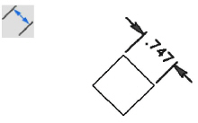
These tools measure space or objects, obliquely or point to point. To access this subpalette, tear off the Dimension palette from the main tool bar.
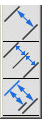
This tool dimensions an object or space from point to point or obliquely.
Using the Oblique Dimension Tool
1. Select the Oblique Dimension tool. The Message Line reads, Oblique: Pick first dimension point. The Message Line guides each successive step.
2. Click the left point first.
3. Click the right point. The dimension appears. Drag it to a new location. Dimension and extension lines automatically redraw.
Click the points in the opposite order to display the dimension on the other side of the objects.
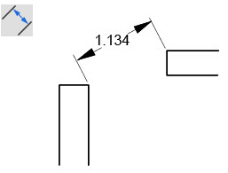
Oblique Base Line Dimension Tool
This tool dimensions objects and spaces point-to-point or obliquely from a base point. The results shown reflect colinear dimension points.
Using the Oblique Base Line Dimension Tool
1. Select the Oblique Base Line Dimension tool. The Message Line reads, Oblique Base Line: Pick first dimension point. The Message Line guides each successive step.
2. Click the base point of the geometry.
3. Click the second point. The dimension appears.
4. Click the next place for the dimension. This dimension appears to the right of the first, measured from the base point. Continue clicking all the points to be dimensioned. Drag each dimension to a new location. Dimension and extension lines automatically redraw.
Click the points in the opposite order to display the dimension on the other side of the objects.
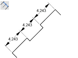
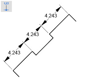
This tool dimensions objects and spaces point-to-point, end-to-end. The results shown reflect colinear dimension points.
Using Oblique Chain Dimension Tool
1. Select the Oblique Chain Dimension tool. The Message Line reads, Oblique Chain: Pick first dimension point. The Message Line guides each successive step.
2. Click the first point on the geometry.
3. Click the second point. The dimension appears.
4. Click the next place for the dimension. This dimension appears, measured from the last point clicked. Continue clicking all the points to be dimensioned. Drag each dimension to a new location. Dimension and extension lines automatically redraw.
Click the points in the opposite order for the dimension to display on the other side of the objects.
Tip: To access the subpalette, tear off the Dimension palette from the main tool bar.
These tools measure an object or space perpendicular to another line. If most of the dimensions start from a line edge, use this tool to generate both horizontal and vertical dimensions.
For 3D geometry, perpendicular dimensions are created in the plane of the baseline. To access this subpalette, tear off the Dimension palette from the main tool bar.
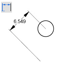
This tool dimensions an object or space perpendicular to a line.
Using the Perpendicular Dimension Tool
1. Select the Perpendicular Dimension tool. The Message Line reads, Perpendicular: Pick first dimension point. The Message Line guides each successive step.
2. Click the base line. Be certain to click on the base line, not on the endpoint of the base line.
3. Click the object or location.
The dimension appears. Drag it to a new location. Dimension and extension lines automatically redraw.
Click the points in the opposite order to display the dimension on the other side of the objects.
Tip: To access the subpalette, tear off the Dimension palette from the main tool bar.
Perpendicular Base Line Dimension Tool
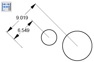
This tool dimensions between a point or object perpendicular to an existing base line.
Using the Perpendicular Base Line Dimension Tool
1. Select the Perpendicular Base Line Dimension tool. The Message Line reads, Perpendicular Base Line: Pick first dimension point. The Message Line guides each successive step.
2. Click the base point of the geometry.
3. Click the second point. The dimension appears.
4. Click the next place for the dimension. This dimension appears above the first, measured from the base point. Continue clicking the points to be dimensioned. Drag each dimension to a new location. Dimension and extension lines automatically redraw.
Click the points in the opposite order to display the dimension on the other side of the objects.
Perpendicular Chain Dimension Tool
This tool dimensions between points or objects perpendicular to an existing baseline.
Using the Perpendicular Chain Dimension Tool
1. Select the Perpendicular Chain Dimension tool. The Message Line reads, Perpendicular Chain: Pick first dimension point. The Message Line guides each successive step.
2. Click the first point on the geometry.
3. Click the point. The dimension appears.
4. Click the next place for the dimension. This dimension appears, measured from the last point clicked. Continue clicking all the points to be dimensioned. Drag each dimension to a new location. Dimension and extension lines automatically redraw.
Click the points in the opposite order to display the dimension on the other side of the objects.
Perpendicular Ordinate Dimension Tool
This tool dimensions between a point or object perpendicular to an existing base line.
Using the Perpendicular Ordinate Dimension Tool
1. Select the Perpendicular Ordinate Dimension tool. The Message Line reads, Perpendicular Ordinate: Pick first dimension point. The Message Line guides each successive step.
2. Click the base point of the geometry.
3. Click the next point. The dimension appears, measured from the base point.
4. Click the next point for the dimension. This dimension appears measured from the base point. Continue clicking all the points to be dimensioned. To display a dimension at the base point, click the base point after having dimensioned all other points.
Drag each dimension to a new location. Dimension and extension lines automatically redraw.
Reminder: To display the dimension number of the base point click both the first and last dimension points.
Radial & Diametral Arrow Dimension Tools
These tools measure the radial or diameter, placing the arrow inside or outside the object as designated by the appropriate tool name.
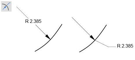
Radial Arrow Out Dimension Tool
This tool measures the radius of a circle, arc, or fillet.
Using the Radial Arrow Out Dimension Tool
1. Select the Radial Arrow Out Dimension tool. The Message Line reads, Radial Arrow Out: Select arc/circle. The Message Line guides each successive step.
2. Click near the circle, arc or fillet to be dimensioned. Click inside or outside the object depending on where the dimension should appear.
The dimension is placed for the selected object. When the dimension appears the leader line is placed at the nearest 15° increment from the location clicked. Drag the text to a new location.
For 3D geometry, radial dimensions are created in the plane of the arc or fillet.
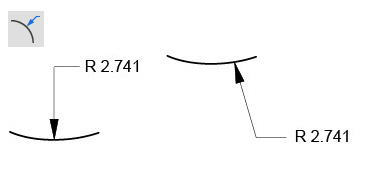
Radial Arrow In Dimension Tool
This tool measures the radius of a circle, arc, or fillet with the arrow inside the geometry.
Using the Radial Arrow In Dimension Tool
1. Select the Radial Arrow In Dimension tool. The Message Line reads, Radial Arrow In: Select arc/circle.
2. Click near the circle, arc or fillet to dimension. Click inside or outside the object depending on where the dimension should appear. Either way the arrow line starts from the arc center.
The dimension text appears for the object. The arrow line starts from the arc center. When the dimension appears, the leader line is placed at the nearest 15° increment from the location clicked. Drag the text to a new location.
For 3D geometry, radial dimensions are created in the plane of the arc or fillet.
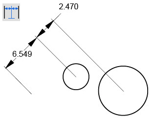
Diametral Arrow Out Dimension Tool
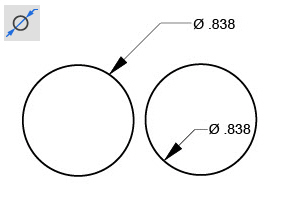
This tool measures the diameter of a circle.
Using the Diametral Arrow Out Dimension Tool
1. Select the Diametral Arrow Out Dimension tool. The Message Line reads, Diametral Arrow Out: Select arc/circle.
2. Click near the circle or arc to be dimensioned. Click inside or outside the object depending on where the dimension should appear.
The dimension appears for the object. When the dimension appears, the leader line is placed at the nearest 15° increment from the location clicked. Drag the text to a new location. Change the position of the arrow by dragging a selection fence around the control point at the tip of the arrow, and then dragging the arrow to a new location.
For 3D geometry, diametral dimensions are created in the plane of the circle.
Diametral Arrow In Dimension Tool
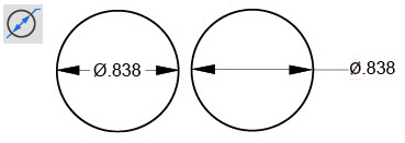
This tool measures the diameter of a circle.
Using the Diameter Arrow In Dimension Tool
1. Select the Diametral Arrow In Dimension tool. The Message Line reads, Diametral Arrow In: Select arc/circle.
2. Click near the circle or arc to be dimensioned. Click inside or outside the object depending on where the dimension should appear.
The dimension appears for the object (depending on the circle and font size). When the dimension appears, the leader line is placed at the nearest 15° increment from the location clicked. Drag the text to a new location.
For 3D geometry, diametral dimensions are created in the plane of the circle.

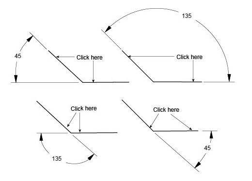
This tool measures the angle between two lines.
Using the Angular Dimension Tool
1. Select the Angular Dimension tool. The Message Line reads, Angular: Pick first line. The Message Line guides each successive step.
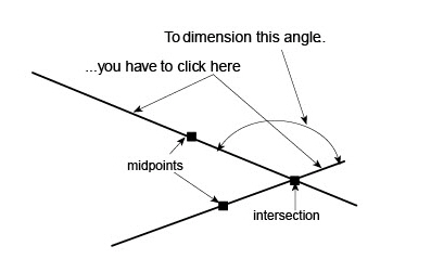
2. Click on the first line near the endpoint from which the angle is measured.
3. Click near the endpoint of the second line.
The inside angle is measured between the lines. The smaller angle is used.
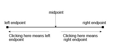
The angle between the endpoints of the lines is measured so that it is necessary to only click near the end points, not exactly on them. Graphite interprets all mouse clicks left of the line midpoint as the left endpoint and all mouse clicks right of the line midpoint as the right endpoint.
When dimensioning intersecting lines it is important to not confuse the intersection with the midpoint of the lines.
If the lines don’t meet, the angle is measured from the invisible extension of the lines. The extension appears as part of the dimension.
When the dimension text appears, drag it to a new location. When releasing the mouse button, the dimension and extension lines are redrawn.
Angular dimension displays all angles properly if the angles are larger than 3 degrees. For smaller than that, build the dimensions manually using lines and text objects.
The Angular Dimension tool does not dimension angles over 180°.
For 3D geometry, Angular dimensions are created in the plane of the two lines.
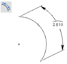
This tool measures the length of an arc.
Using the Arc Length Dimension Tool
1. Select the Arc Length Dimension tool. The Message Line reads, Arc Length: Pick start point on the arc. The Message Line guides each successive step.
2. Select the start point.
3. Select a point on the arc.
4. Select the opposite end of the arc.
Drag the text to the desired position.
The Arc Length Dimension tool does not put witness lines perpendicular to the arc for angles less than 180 degrees.
Circle Center Line Dimension Tool
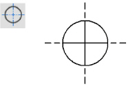
This tool creates a center line for any circle being created. It also optionally displays a thread symbol with the center line.
Using the Circle Center Line Dimension Tool
1. Choose the Circle Center Line tool. The Message Line reads, Circle Center Line: Select circle.
2. Click on the circle with the tool.
Pressing the CTRL (Windows) or the OPTION (Macintosh) key while clicking on the circle adds a thread symbol.
3. In the Axis overlap data field of the Status Line, enter the desired axis overlap.
4. Press the ENTER (Windows) or the RETURN (Macintosh) key.
A circle center line with an optional thread symbol is added to the circle with the specified overlap.
The Status Line sets the Axis overlap.

This tool attaches a balloon symbol to geometry in the location clicked.
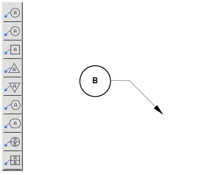
Using a Balloon Dimension Tool
1. Select the Balloon Dimension tool. The Message Line reads, Balloon: Pick geometry to point to. The Message Line guides each successive step.
2. Click the point on the geometry for the dimension arrow.
3. Click the second point to specify the location of the balloon.
The balloon symbol appears.
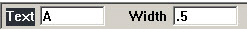
4. Enter the text and frame width in the Status Line data fields. Press ENTER (Windows) or RETURN (Macintosh) to update the dimension.
Move the dimension by dragging the text to a new location.
Balloon dimension text does not increment while placing additional balloons. Enter specific text in the balloon dimension, if necessary.
The Status Line contains Text and Width data fields.
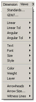
Graphite automatically creates dimensions according to ANSI Y14.5, DIN, ISO or JIS standards. Many companies and individuals, however, have developed their own standards. The commands in the Dimension menu control virtually every aspect of the dimension appearance, without having to construct dimensions manually and while retaining the associativity of Graphite’s smart dimensions.
Settings made in the Dimension menu affect the currently selected dimension and all future dimensions.
Tip: To change from decimal to fractional dimensions use Layout>Preferences>Units.
Fractional Display or Decimal Display
To change the current linear appearance of the dimensions, first change the precision setting in the Units dialog box.
Choose Layout>Preferences>Units. In the Units dialog box, change the Precision to a decimal or fractional option by holding down the mouse button on the arrow to the right of the data field and scrolling to the desired precision. That precision is now displayed in the Status Line data fields.
Graphite still calculates out to sixteen decimal places, however, the Status Line displays the nearest fraction or decimal to the calculated value based on the precision selected.
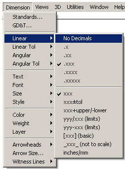
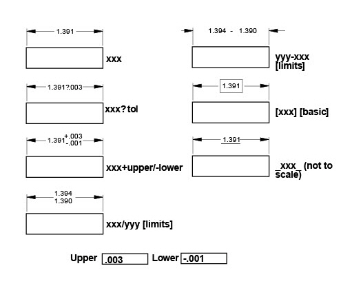
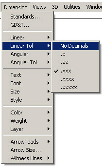
This command in the Dimension menu sets the precision of the dimension’s nominal value, and the format of its tolerance and limits. Dimensions may be shown as either decimals or factions, as designated in the Preferences settings. The default is decimals with three decimal places (or x/16 if set to fractions) with no tolerance or limits
.
The following graphic shows the appearance of each tolerance format, the limits shown in the Status Line bellow are entered.
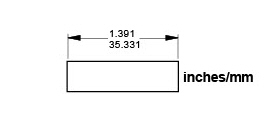
Dual dimensioning displays the dimensions in both inches and millimeters by selecting the inches/mm under Dimensions>Linear
.
The Linear Tolerance command in the Dimension menu sets the precision of a linear dimension's tolerance values.
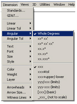
The Angular command in the Dimension menu sets the format for Angular dimensions.
It is possible to set degrees, minutes and seconds as well as the tolerance and limits for these dimensions.
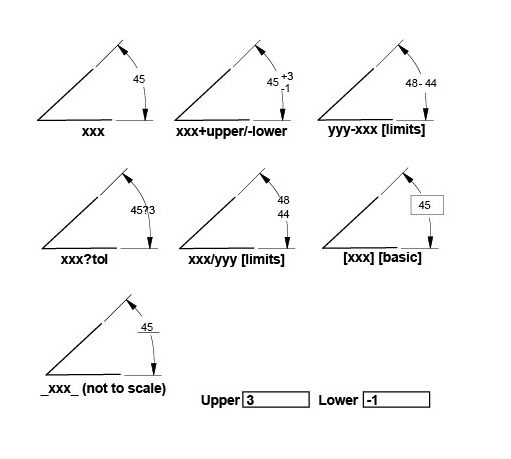
The default format is degrees with no minutes or seconds and no tolerance or limits. The graphic here shows the appearance of each tolerance format as if entered with the limits shown in the Status Line.
Tech Note: Use the [xxx] (basic) format to create dimensions for GD&T symbols.
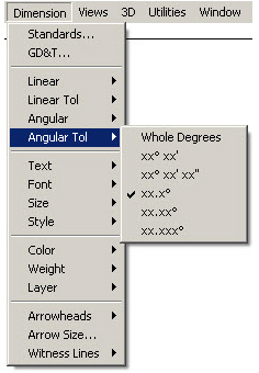
The Angular Tolerance command in the Dimension menu sets the precision of an angular dimension’s tolerance values.
Characteristics set here affect dimensions only. To change the style of text within text boxes, use the Text menu.
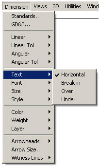
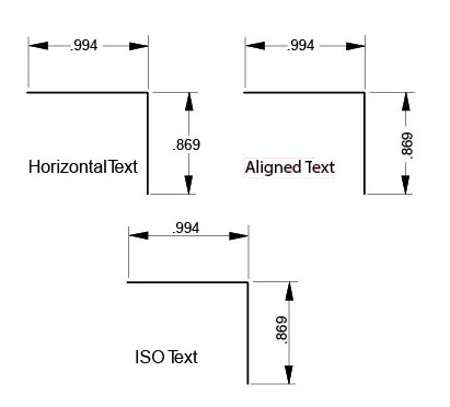
The Text command in the Dimension menu specifies the position and orientation for dimension text.
The default is Horizontal text. The Break-in, Over and Under options produce text that is aligned with dimension leader lines. Over and Under display text above or below leader lines, while Break-in places the text between leader lines.
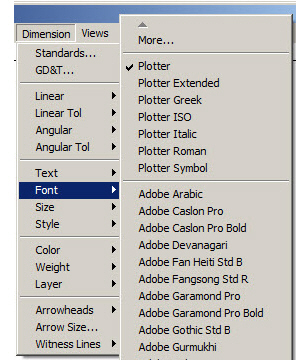
The Font command in the Dimension menu picks the font for dimension text. The fonts in this list are the same as those available in the Font submenu from the Text menu.
Windows: additional fonts are accessed by choosing the More command.
Tech Note: The Font command only affects dimensions. To change the font of other text objects, choose Text>Font.
The Font submenu in the Text menu has no effect on dimensions. Use the Font command from the Dimension menu to specify the font for dimension text.
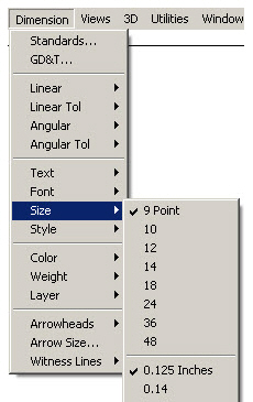
The Size command in the Dimension menu picks the size of dimension text only. The sizes in this list are the same as those available in the Size submenu from the Text menu.
Selecting the Other option specifies a non-standard font size for dimension text.
Tech Note: The Size command only affects dimensions. To change the size of other text objects, use Edit Objects or the Size submenu from the Text menu. The size submenu from the Text menu has no effect on dimensions.
The Style command in the Dimension menu designates the style of dimension text. The styles in this list are the same as those available in the Style submenu from the Text menu, however, the settings here do not affect those in the Text menu.
Tech Note: The Style command only affects dimensions. To change the style of other text objects, use the Style submenu from the Text menu. The Style submenu from the Text menu has no effect on dimensions.
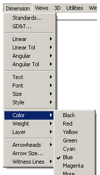
The Color command in the Dimension menu sets the color of the dimension.
The default color is blue.
Tech Note: The Color command only affects dimensions. To change the color of other objects, use Edit Objects or the Color submenu from the Pen menu.The Color submenu from the Pen menu has no effect on dimensions.
The Weight command in the Dimension menu specifies the weight of dimension lines. Dimension lines are typically drawn in the thinnest weight available. For Graphite, that is 0.002" or 0.05mm.
The default weight is 0.002" or 0.05mm.
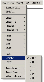
Tech Note: The Weight command only affects dimensions. To change the weight of other objects, use Edit Object or the Weight submenu from the Pen menu.The Weight submenu from the Pen menu has no effect on dimensions.The values shown in the Weight submenu may be different if the available line weights have been changed using the Pen Weight Editor.
The Layer command in the Dimension menu specifies the layer on which dimensions are placed. Dimensions can be placed on any visible layer.
The default layer is the Dimension layer. If the layer on which dimensions are to be placed is hidden or deleted, future dimensions will be placed on the current work layer.
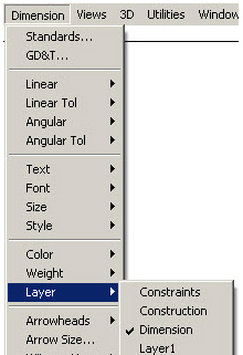
Tech Note: The layers in the list will be different than the ones shown here if layers have been added or any of the default layers have been deleted.
The Arrowheads command in the Dimension menu sets the type of arrowhead used for dimensions.
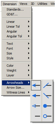
Tech Note: The Arrowheads command only affects dimensions. To select the arrowhead type for lines or arcs, use the Arrowheads submenu from the Pen menu. The Arrowheads submenu from the Pen menu has no effect on dimensions.
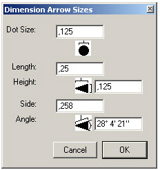
The Arrow Size command in the Dimension menu specifies the size of the arrowhead that has been selected.
|
By changing any value in the Length, Height, Side, or Angle entry data fields, Graphite changes the values in the other entry data fields accordingly.
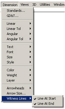
The Witness Lines command in the Dimension menu designates which sides of the linear dimension should have witness lines. A check mark indicates that a witness line is placed at the specified location. This option is useful for plotting a drawing that contains baseline or chain dimensions. By turning off one or more of the overlapping witness lines, the plotter is prevented from drawing multiple witness lines when only one is needed.
The Start of a dimension is the first point clicked. The End of a dimension is the last point clicked. The default settings have witness lines at both the start and end of a dimension.
This command affects only linear dimensions. Radial and diametral dimensions are not affected by the settings made in the Witness Lines command.
Tip: Witness Lines for existing linear dimensions can also be toggled on or off in Edit Objects.
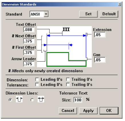
The Dimension Preferences dialog box is opened by choosing Dimension>Standards. This dialog box sets the standard that the dimensions will follow, as well as defines the characteristics for the standard. Most changes made in the Dimensions Standards dialog box affect currently selected dimensions and newly created ones. Changes made to the First Offset and the Next Offset affect only newly created dimensions.
Changing the standard also changes the Dimension menu settings. Setting dimension standards saves the values in the Dimension Standards dialog box as well as the settings in the Dimension menu, except for the Witness Lines command.
|
Clicking OK accepts the changes made and closes the Dimension Standards dialog box. Clicking Apply affects any changes made in the Dimension Standards dialog box to any currently selected dimensions without closing the dialog box. Clicking Cancel ignores any changes and closes the Dimension Standards dialog box.
See GD&T for information about the U.S. government standard called Geometric Dimensioning and Tolerancing.
Objects must be dimensioned in order to use the parametrics feature. Specify values, variables, or expressions for each dimension. Parametrics are discussed in detail in Parametrics.
Creating a Parametric Dimension
1. Create the dimension as usual.
The Status Line displays a # symbol in the text data field.
2. Enter a value (variable or algebraic expression) in the text data field.
The dimension reflects the value or variable entered, regardless of the actual value of the geometry just dimensioned.
3. Continue dimensioning as needed to define the part completely.
4. Use the parametric feature as described in Parametrics.
Converting Parametric Dimensions to Associative Dimensions
When bringing in a parameterized part with the Import command, the geometry is drawn as specified, but the dimensions display the variables and expressions which defined them as symbols. It is possible to change the dimensions to be associative so that they reflect the actual measurements of the geometry, even if the geometry is changed.
1. Select the dimensions.
2. Choose Edit>Edit Objects.
3. Enter a # in the text data field.
4. Click Apply and close the dialog box.
The parametric variable changes to reflect the geometry’s actual measurement.