


Adding Details
Once the basic geometry is created, add notations or highlight certain portions of the geometry. This chapter discusses a few ways to do so. The topics covered include:
• Text
• Crosshatching and Solid Fills
When the drawing needs to be annotated, use the Text tool to create a text box for entering characters from the keyboard. Create, import and edit text on the screen, using the Text menu to set the characteristics, such as font, text size, style, alignment, line spacing and indent.
There are nine text handles for each text object. These help move and/or align the text as necessary.
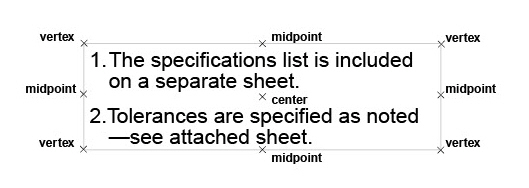

The Text tool, creates and edits text on screen. The text entered has the characteristics set in the Text menu.
1. Select the Text tool from the tool palette. The Message Line reads, Text: Pick opposite corners of text entry box [Ctrl = Copy Previous (Windows) or Option = Copy Previous (Macintosh)].
2. Create a text box by dragging or by clicking two locations to place the opposite corners of the text area.
The text box is as tall as a single line of text and as wide as indicated. The text cursor appears in the box, ready for the typing.
3. Enter the desired text from the keyboard.
Pressing the BASKSPACE (Windows) or the DELETE (Macintosh) key erases characters to the left of the cursor.
The text entered automatically word wraps to the next line when it reaches the right side of the text box created in step #2. If the text box is resized, the words rewrap automatically.
The Status Line specifies the X and Y location of the first text box corner, the text box width and height.

Small portions of text may be copied and pasted into a text box from other sources such as a word processing document.
Tech Note: An ASCII text file is usually created by word processing software and saved as plain text. It usually contains only standard keyboard characters—letters, numbers, punctuation, and spaces—without the formatting typically found in word processing documents.
It is also possible to import an ASCII file that contains text into the drawing. For example, place specifications written with a word processor on the drawing without retyping them. The entire file imports, so to use only part of the document, create a new file that contains only the information to be entered on the drawing. To import a file:
1. Select the Text tool from the tool palette.
2. Create a text box by dragging or clicking twice to place the opposite corners of the text area.
3. Choose File>Import.
A dialog box appears.
4. Select the text file to import.
When the Import dialog box appears, specify the Text as the file type.
5. Click OK.
The text file appears in the text box created.
1. Select the Text tool from the tool palette.
2. Move the pointer directly over the text to be edited. The pointer turns into an I-beam text cursor when it is over text. (This only occurs when the Text tool is active.)
3. Use the text cursor to select text.
Drag either direction to select characters, double-click on an individual word to select it, or click to place the text cursor within the existing text to add or change it.
4. Modify the selected text by choosing the appropriate commands from the Text menu.
Tip: To change characteristics for the entire text entry, use the Selection tool to select the text block.
Changing the Characteristics of a Block of Text
Change the font, text size, style, spacing and indentation of a block of text.
1. Use the Selection tool to select the block of text to be changed.
2. Select the new characteristic from the Text menu.
The selection shows the new characteristic.
Tip: To change the characteristics of a word or portion of a text block, use the Text tool to select what to change.
Changing the Size of the Text Box
1. Click the Selection tool.
2. Drag a selection fence around the right side of the text box.
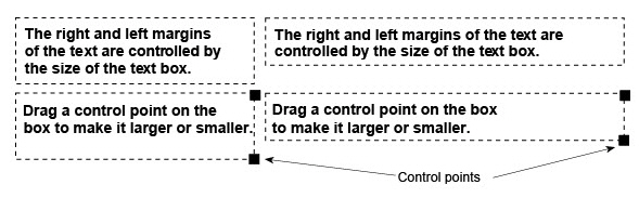
The dotted lines shown in the following graphic do not appear on the screen.
Note: For single lines of text, if it is not possible to select the control points on the right side of the text box, it may be that the original text box extends further than the edge of the text. With the Selection tool, first select the text by clicking on it. When the text box appears, drag a selection fence around the right side.
The control points mark the boundaries of the text box when it is first created.
3. Drag the control points to the right as shown below or to the left to make the text box smaller.
The area changes size and the text rewraps automatically.
In the Edit menu, Selectable Points must be active for selecting the control points of the text box.
1. Choose the Selection tool.

2. Select the text object to move.
3. Move the cursor over the text object. The cursor becomes a 4-way Move symbol.

4. Place the 4-way Move symbol at the desired handle location using the Drafting Assistant notations as a guide.
5. Drag the text object to the new location.
To spell check any text item in a drawing:
1. Select the text to check.
2. Access the spell check function using one of the following:
• Choose Text>Spell Check.
• Right click the mouse and choose Spell Check from the context menu that appears.
• Choose Spell Check tool from the Text palette.

3. The Spell Check dialog box operates like any spelling checker. It is necessary to have the required files in the directory named “Spell” of the Graphite application folder. The user requested additions are compiled in the userdic.tlx file.
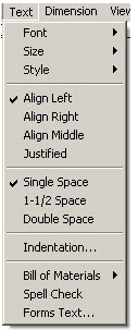
The Text menu contains commands for changing the text font, size, and style, as well as the justification, spacing and indentation.
The Font command in the Text menu changes the font for selected text or future text entries.
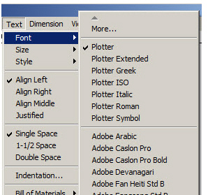
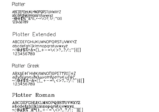
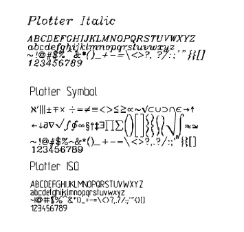
The fonts listed in the menu are those installed on the computer and include Ashlar-Vellum’s Plotter fonts. Use a Plotter font whenever creating text for a drawing that is intended to be sent to a plotter, since plotting Postscript or TrueType fonts take much more time to plot or may be substituted.
The selected font stays in effect for the current document until another font is chosen.
Note: The fonts used for dimensions are the same set of fonts as those used for the text, however, they are set in the Dimension menu.
Special characters and accents are available as described in Appendix B: Special Characters.
Extended Font Selection (Windows)
The Font submenu displays up to 20 fonts. If more than 20 fonts are installed, select More in the Font submenu of the Text menu for more available fonts.
Tech Note: Macintosh users: All fonts available in the system are displayed in the fonts list so there is no Extended font selection process.
Choosing More brings up a dialog box for specifying the font, text size and text style. The text size is measured as a point size. To specify the size in the units set for the drawing, type the exact unit such as " for inch or mm for millimeter after the value.
1. Choose Text>Font>More.
The Character Format dialog box displays:
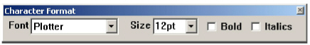
2. Select the character format.
3. Click Apply.
Leave this dialog box open to assign other character formats. To close this dialog box, double click the Control pull-down menu in the upper left corner of the dialog box.
The character format specified stays in effect until another character format is chosen.
Text, including Postscript and TrueType fonts, can be rotated with the Rotate tool like any other object in the drawing. Text that is neither horizontal nor vertical may appear jagged on the screen, but it should print at the system’s highest quality.
A typical system font specified for .156 inches may produce a character that is only .125 inches. The variation depends on the proportional spacing of the font. To set a font to exact specifications, use a Plotter font, which conforms to ANSI standards.
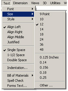
The Size command in the Text menu sets the font size for the selected text or for future text entries in the current document. This can be specified as either points (12 pt) or units (.156 inches) as defined in the Units dialog box within Layout>Preferences>Units. If no unit is specified, Graphite picks the default unit.
Specifying a Non-standard Text Size
Choosing Other from the Size submenu brings up a dialog box to enter the exact text size in point size, inches or metric units. If a unit is not specified the default unit for the drawing is used.
1. Choose Text>Size>Other.
2. Enter the size. The size is measured in the current units as set in the Preferences submenu. To specify a point size, include pt with the numeric entry.
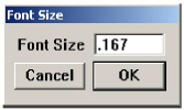
3. Click OK.
The size specified stays in effect until another size is chosen.
Making changes to the scale in the Drawing Size dialog box in the Layout menu, changes the text size inversely. For example, if the drawing is scaled 1:4, multiply the text size by 4 for it to display properly on the drawing. Also use the Keep Text Size and Keep Dimension Text Size options from the Drawing Size dialog box when changing the Drawing Scale to change the size of the text relative to the size of the other objects.
If it looks right on the screen, the scaling is appropriate. See the chapter on Graphite Documents for more information on scaling.
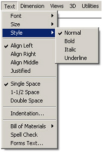
The Style command in the Text menu sets the style (such as Bold or Underline) for selected text or future text entries.
The style specified stays in effect until another style is chosen. A check mark indicates the current style. Change the default setting by saving the changes in the preferences file (prefs.vc6 - Windows, or Graphite prefs - Macintosh). Choose Layout>Preferences>Save Preferences.
The four commands in the second section of the Text menu align the text within the text box. The text can be aligned on the left, the right, centered in the middle, or it can be fully justified so that it is aligned with both left and right margins of the text box.
If the Text tool is active, both the selected text and future text are aligned as specified, but existing text is not aligned. If another tool is active when any of these commands are chosen, only future text entries are aligned. If a text entry is selected when any of these commands are chosen, the selection and future text entries are aligned as specified.
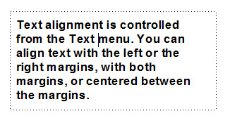
Align Left in the Text menu aligns the selected and future text at the left margin of the text area.
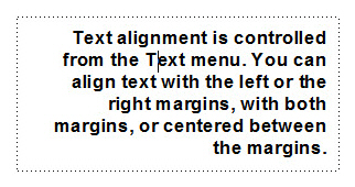
Align Middle centers the selected and future text in the text area.
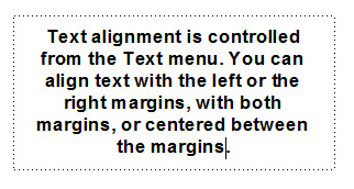
Align Right aligns the selected and future text at the right margin of the text area.
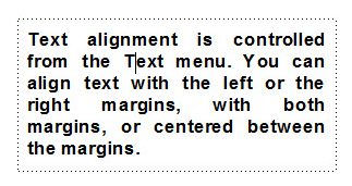
Justified aligns both the left and right margins of the selected and future text in the text area.
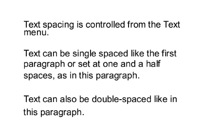
The Text menu has commands for single, space-and-a-half, or double spacing between the lines of the text.
The check mark in the Text menu indicates the current line spacing. Change the default setting by saving changes in the Preferences file.
Single Space sets the spacing of selected and future lines of text so each line occupies one space in the text area.
This command changes the spacing of selected and future text so each line occupies one and a half spaces in the text area.
This command sets the spacing of selected and future text so each line occupies two spaces in the text area.
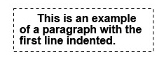
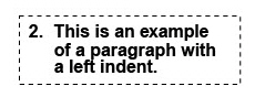
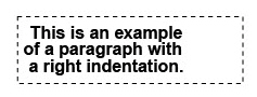
To indent the text on the right or left side of the text box, or to have the first line indented, choose Text>Indentation.
The indentation command in the Text menu sets the indentation of paragraphs for the selected text area as defined by the units set in the Preferences submenu.
1. Choose Text>Indentation.
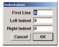
The dialog box appears.
2. Specify the indentation. Use point values if pt is included in the entry.
3. Click OK.
Specify the number of units for any or all the choices:
|
All TrueType and PostScript fonts installed on the computer are available in Graphite. (SHX fonts are not supported on the Macintosh platform.)
In addition, Graphite offers the following Plotter fonts.
Graphite can crosshatch and fill any enclosed area in the drawing and then automatically update the crosshatching or fill when changing the dimensions of the enclosed area. If a closed area with a hole or other cutout in it is specified, Graphite accurately excludes the hole area from the crosshatching.
In the Pen menu are two fill commands: Solid Fill and Fill, and two crosshatch commands: Crosshatch and Hatch. Fill creates a solid fill for a selection with the current pen color. Hatch crosshatches the selection with the default pattern or the last pattern selected. Solid Fill sets the tolerance for the fill. To change the hatch patterns, choose Crosshatch and specify the pattern to use. To change the default hatch pattern, make changes to the preferences file as described in Chapter 5, Basic Environment Settings.
Choose the Fill command from the keyboard with CTRL+B (Windows) or z+B (Macintosh) and the Hatch command from the keyboard with CTRL+H (Windows) or z+H (Macintosh).
Tech Note: Crosshatching appears parallel to the work plane and only in the view in which it was created. In other words, it is drawn correctly when viewed along the z-axis of the work plane.
A wide variety of Crosshatch patterns are available in both ISO or DIN styles. Crosshatching appears parallel to the work plane, and only in the view in which it is created. In other words, it is drawn correctly when viewed along the z-axis of the work plane.
The following ISO crosshatching options are available.
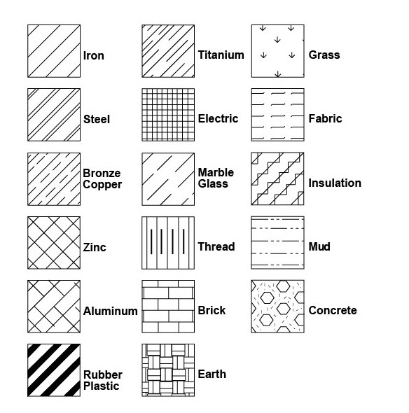
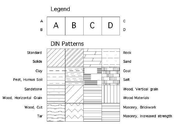
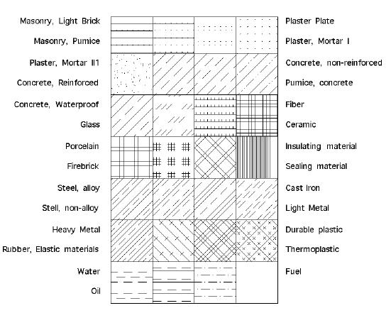
The following DIN crosshatching options are available.
Specifying the Fill or Crosshatch Area
Tech Note: To crosshatch Smart Walls containing smart symbols, first segment the walls to create hatch boundaries. Since smart symbols cover only wall segments, they can’t be used as hatch boundaries.
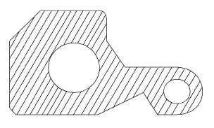
The selected objects must completely enclose the area that needs to be crosshatched or filled. For example, to crosshatch or fill the object below; select all of the lines making up the part, including the holes.
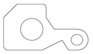
The exterior lines define the boundary for the crosshatching or solid fill. The two holes tell Graphite that those enclosed areas within the original area should not be crosshatched or filled.Once the lines and holes are selected, in the Pen menu, choose the Hatch, Fill, Crosshatch, or the Solid Fill command and specify the pattern to use.
Tip: To crosshatch a figure that is not a closed figure, add lines or segment lines to make a closed figure. In this way, crosshatch individual sections of the geometry. See “Crosshatching” in the “Advanced Features” section of the Getting Started manual for a step-by-step example.
It is important not to select extra objects when specifying the crosshatch or fill area because Graphite does not know how to treat the extra objects.
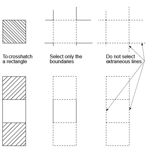
Tip: Use the Tracer tool to select the boundary.
The Crosshatch command in the Pen menu crosshatches the selection with one of the industry standard crosshatching patterns. Change the default pattern by saving changes in the preferences file. See Basic Environment Settings
1. Select the objects which represent a closed boundary. The closed boundary may include cutout areas such as a hole. Select both the outside boundary and the hole.
2. Choose Pen>Crosshatch.
The dialog box appears displaying DIN crosshatching options.
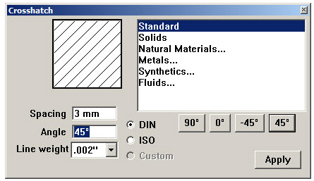
3. To display ISO crosshatching options, click the ISO radio button in the dialog box.
1. Click the ISO radio button to display the ISO patterns. The dialog box displays.
2. Select the pattern from the menu.
The pattern selected appears in the Pattern display area as it will appear on the drawing.
3. Change the spacing and angle, if desired.
When making changes to the angle or spacing, the pattern box shows the revised pattern exactly as it is when the specified object is crosshatched.
4. Click Apply.
1. Select the pattern from the menu. Those patterns that have an ellipsis (...) following their name have their own submenu. Double-click on one of those names to display the submenu.
To return to the main menu, double-click on the ellipsis at the top of the submenu.
The pattern selected appears in the Pattern display area as it appears on the drawing.
2. Change the spacing and angle, if desired.
When making changes to the angle or spacing, the pattern box shows the revised pattern exactly as it is when the specified object is crosshatched.
3. Click Apply.
Editing an Existing Crosshatch Pattern
1. Select the existing crosshatching by clicking it with the Selection tool.
2. Choose Pen>Crosshatch.
3. Make the changes in the Crosshatch dialog box.
4. Click Apply.
The crosshatching changes as specified.
Note: The line style of any specific crosshatch pattern is not editable. Only the space and angle can be adjusted.
CTRL+H (Windows); z+H (Macintosh)
The hatch command, located in the Pen menu, crosshatches the selected objects using the current crosshatch pattern. To change the crosshatch pattern, choose Crosshatch and make the selection from the dialog box.
The best way to select a hatch boundary is with the Tracer tool.
Crosshatching with the Current Pattern
1. Select the object to crosshatch.
2. Choose Pen>Hatch.
The selected area is crosshatched with the current pattern.
The Solid Fill command in the Pen menu fills the selection with the current pen color.
A solid filled object covers its background only if it is the last entity drawn. To make a solid filled object cover its background, select it again before printing or saving to bring it on top.
1. Select the objects which represent a closed boundary. The closed boundary may include cutout areas like a hole. Select both the outside boundary and the hole.
2. Choose Pen>Solid Fill. The Fill dialog box appears.
3. Enter a Tolerance for the fill.
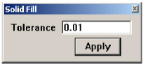
The tolerance controls how smooth the linearization is for fills in circles, arcs, ellipses and closed splines. Increasing the value of Tolerance makes the fill smoother. The default value is 0.01 (A value of 0.001 produces smoother edges than .01. This is also affected by Drawing Scale.)
4. Click Apply.
The selected object fills with the current pen color.
Changing the Color of an Existing Solid Fill
1. Select the existing solid fill by clicking it with the Selection tool.
2. In the Pen menu, choose a new color from the Color submenu.
The Fill color changes as specified and is visible as soon as the solid fill is deselected.
Changing the Tolerance of an Existing Solid Fill
1. Select the existing solid fill by clicking it with the Selection tool.
2. Choose Pen>Solid Fill.
3. Change the Tolerance and press Apply.
The Tolerance may also be changed using the Edit Objects dialog box.
CTRL+B (Windows); z+B (Macintosh)
This command is located in the Pen menu and fills the selected objects using the current pen color. To change the fill color, in the Pen menu, change the color from the Color submenu.
Fill with the Current Pen Color
1. Select the object to fill.
2. Choose Pen>Fill.
The selected area fills with the current pen color.
To use arrowheads on lines or circular arcs that are not a part of dimensions, specify the placement of arrowheads in the Pen menu. An arrowhead may appear at the beginning or end of a line or circular arc, or at both the beginning and end.
Tech Note: Arrowheads for dimensions are controlled with commands from the Dimensions menu.
The width of the arrowhead is based on the text size.
Use the Arrowheads submenu to set one of eight arrowheads for arrow lines.
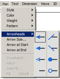
Tech Note: The size of the dimension arrowheads is set using the Arrow Size command from the Dimensions menu.
This command in the Pen menu places an arrowhead at the beginning of any selected and subsequent lines and circular arcs. Choose the type of arrowhead from the Pen menu. A check mark indicates the current arrowhead setting. Change the default setting by saving changes in the preferences file.
This command in the Pen menu places an arrowhead at the end of selected and subsequent lines and circular arcs. Choose the type of arrowhead from the Pen menu. A check mark indicates the current arrowhead setting. Change the default setting by saving changes in the preferences file.
The start and end of a line and an arc are determined by the point that was created first.
Tip: Add or remove arrows to or from lines and arcs using the Edit Objects dialogue box.