


Once an object is created, alter it by selecting it and choosing a command or a tool to edit it. This chapter describes the common editing activities to perform on a selected object and compares different methods for performing the same action.
The specific topics covered are:
• Changing the Characteristics of Objects
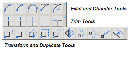
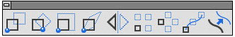
These tools are used to change an object physically, either by altering the geometry, changing the size, changing the location, or modifying orientation of the selected object. Three subpalettes on the tool palette provide these editing capabilities.
|
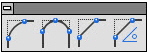
These tools construct fillets and chamfers from corners formed by nonparallel lines or curves. The fillets and chamfers are automatically trimmed, unless the CTRL (Windows) or the OPTION (Macintosh) key is held down while selecting the objects.

The 2-Entity Fillet tool constructs an arc tangent to the two objects clicked. Fillets use the smallest arc between the selected geometry.
Using the 2-Entity Fillet Tool
1. Click the 2-Entity Fillet tool. The Message Line reads, 2-Entity Fillet: Pick first entity [Shift = Corner, Ctrl = No trim (Windows) or Option = No trim (Macintosh)]. The Message Line guides each successive step.
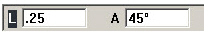
2. Enter the arc radius in the Status Line. The default radius is .25 inch.
3. Select the first entity.
4. Select the second entity. The fillet is created.
Another method is to hold down the SHIFT key and click once inside the desired corner to be filleted. By holding down the CTRL (Windows) or OPTION (Macintosh) key while selecting the objects to fillet, the objects are not trimmed. These options are noted in the Message Line.
The Status Line specifies the Radius of the fillet either before or after creating the fillet.


The 3-Entity Fillet tool constructs a fillet tangent to the three objects chosen.
Using the 3-Entity Fillet Tool
1. Click the 3-Entity Fillet tool. The Message Line reads, 3-Entity Fillet: Pick first entity [Ctrl = No trim (Windows) or Option = No trim (Macintosh)]. The Message Line guides each successive step.
2. Click the three objects to fillet.
By holding down the CTRL (Windows) or OPTION (Macintosh) key while selecting the objects to fillet, the objects are not trimmed.
There are no Status Line entries.

The 2-Entity Chamfer tool creates a chamfer across a corner at the specified distance from the intersection of two lines.
Using the 2-Entity Chamfer Tool
1. Click the 2-Entity Chamfer tool. The Message Line reads, 2-Entity Chamfer: Pick first entity chamfer [Shift = Corner, Ctrl = No trim (Windows) or Option = No trim (Macintosh)]. The Message Line guides each successive step.
2. In the Status Line, enter the distance of the chamfer from the corner. (The default distance is .25 inch.)
3. Click each line making up the corner to be chamfered. Another way is to hold down the SHIFT key and click once inside the corner to chamfer.
The lines are automatically trimmed or extended, unless the CTRL (Windows) or the OPTION (Macintosh) key is held down while selecting the objects.
These options are noted in the Message Line.
The Status Line specifies the distance (length) from the chamfer to the intersection of the corner lines.


The Angular Chamfer tool creates a chamfer at the specified angle and distance from the corner. The specified angle is that between the chamfer and the second line of the corner. The specified length is the distance between the corner and the intersection of the chamfer and the second line of the corner. (The second line of the corner refers to the second line chosen when creating the chamfer).
1. Click the Angular Chamfer tool. The Message Line reads, Angular Chamfer: Pick first entity to chamfer [Ctrl = No trim (Windows) or Option = No trim (Macintosh)]. The Message Line guides each successive step.
2. In the Status Line, enter the length of the intersection of the chamfer and the second line of the corner from the corner. The default length is .25 inch.
3. Enter the angle between the chamfer and the second side. The default is 45°.
4. Click each line making up the corner to be chamfered.
The lines are automatically trimmed or extended, unless the CTRL (Windows) or the OPTION (Macintosh) key is held down while selecting the objects.
The Status Line sets the distance (length) from the intersection as well as the angle.
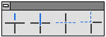
The Trim tools on the tool palette lengthen or shorten lines and curves. In general, select the limiting object(s) before selecting the tool. If you forget to select everything needed, however, hold down the SHIFT key and the Trim tool temporarily becomes the Selection tool so that additional objects can be selected.

The Simple Trim tool shortens a line to the specified boundary. By holding down the CTRL (Windows) or the OPTION (Macintosh) key while using this tool, it becomes the Relimit tool.
Rule: Point to what is to be removed.
1. Select the object that limits the trim.
2. Select the Trim tool. The Message Line reads, Simple Trim: Pick section to trim [Shift = Select boundary, Ctrl = Relimit (Windows) or Option = Relimit (Macintosh)].
If necessary, use SHIFT-Click to select more boundary objects.
3. Click the section of the object to be discarded.
There are no Status Line entries.

This tool lengthens or shortens a line to the specified boundary. By holding down the CTRL (Windows) or the OPTION (Macintosh) key while using this tool, it becomes the Trim tool.
Rule: Point to what is to be kept.
1. Select the object that limits the change.
2. Select the Relimit tool. The Message Line reads, Relimit: Pick section to retain [Shift = Select boundary, Ctrl = Trim (Windows) or Option = Trim (Macintosh)].
If necessary, use SHIFT-Click to select more boundary objects.
3. Click the section of the object to remain.
There are no Status Line entries.

The Segment tool divides a line or curve at intersections with other lines or curves.
1. Select the objects that limit the segmentation.
2. Select the Segment tool. The Message Line reads, Segment: Pick entity [Shift = Select boundary, Ctrl = Current pen (Windows) or Option = Current pen (Macintosh)].
If necessary, use SHIFT-Click to select more boundary objects.
3. Click the object to be segmented.
The selected object segments at the boundary objects. Even though the segmentation cannot be seen on the screen, parts of the segmented line may be selected by clicking.
There are no Status Line entries.
In order to see the segmentation on the screen, first select the boundaries and the object to segment and then choose Layout>Show Points. After the segmentation, the endpoints of the segmented parts are displayed.
By holding down the CTRL (Windows) or OPTION (Macintosh) key while selecting the line to be segmented, the new segment appears in the characteristics of the current pen style.

The Corner Trim tool creates a corner from two specified objects. Lines are extended or shortened to create the corner.
1. Click the Corner Trim tool. The Message Line reads, Corner Trim: Pick first entity to trim [Shift = Corner, Ctrl = No Trim (Windows) or Option = No Trim (Macintosh)]. The Message Line guides each successive step.
2. Click each object.
Another way is to press and hold the SHIFT key and click inside the about-to-be-created corner.
There are no Status Line entries.
Extending Lines to a Theoretical Intersection
To extend a line to its theoretical intersection with another line, first click the line to be extended, then hold down the CTRL (Windows) or OPTION (Macintosh) key and click the line that is not to be trimmed.
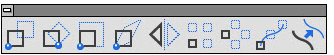
The first part of the Transform & Duplicate palette has the Transformation tools. These tools move, rotate, expand or shrink, stretch, vector-defined and mirror objects. Select the object to transform before selecting a Transformation tool.
It is possible to copy while transforming objects by holding down the CTRL (Windows) or the OPTION (Macintosh) key while specifying the transformation.
By pressing the SHIFT key, additional objects may be selected after Transformation tool is chosen, the tool temporarily becomes the Selection tool so that as soon as the SHIFT key is released the Transformation tool is active again.

The Move tool relocates the selected objects in a new position. Copy the selection by holding down the CTRL (Windows) or OPTION (Macintosh) key while selecting the objects. Select more than one object and they remain in the same position relative to each other.
Referral: Enlarging or shrinking an object with the Move tool is described under Sizing Objects with Tools in this chapter.
1. Select the object(s) to be moved.
2. Select the Move tool. The Message Line reads, Move: Pick beginning reference point [Shift = Select, Ctrl = Copy (Windows) or Option = Copy (Macintosh)].
If necessary, use SHIFT-Click to select more objects.
3. Drag the selected object to a new location, clicking to set a reference point, and releasing to indicate the new location.
Tip: Geometry can be nudged a specified distance within Graphite using the arrow keys on the keyboard. More information on nudging geometry is available further ahead in this chapter.
Another way is to click a reference point, then click a destination point to move the selected object to the new location. It is not necessary for the reference and destination points to be on the object being moved. The move is performed relative to the specified points.
The Status Line specifies the distance for the selection is to be moved in a particular direction.

A positive or negative value entered in a data field of the Status Line determines the direction along the axis. A negative value moves the object to the left or down on the screen. A positive value to the right or up.

The Rotate tool rotates one or more objects around a specified point. Copy the selection by holding down the CTRL (Windows) or OPTION (Macintosh) key while selecting the objects. When selecting more than one object, they remain in the same position relative to each other.
Keep in mind that objects are always rotated about the Z-axis with this tool.
1. Select the object(s) to be rotated.
2. Select the Rotate tool. The Message Line reads, Rotate: Pick center of rotation [Shift = Select, Ctrl = Copy (Windows) or Option = Copy (Macintosh)].
If necessary, use SHIFT-Click to select more objects.
3. Select the center of rotation.
4. Drag the objects or enter an Angle in the Status Line to specify the rotation.
The Status Line specifies the angle of rotation.

Another way is to click the reference point and then click the destination point. It is not necessary for the reference and destination points to be on the object being moved. If they are not, the rotation is performed relative to the specified points.
This tool rotates the selected geometry around an axis through the origin specified and parallel to the z-axis of the work plane. The Object Rotation command rotates around any axis specified.

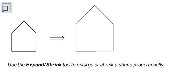
The Expand/Shrink tool resizes objects while maintaining the proportions. Copy the selection by holding the CTRL (Windows) or OPTION (Macintosh) key when selecting the objects. If more than one object is selected, they remain in the same position relative to each other.
Tip: Using the beginning and ending reference point for the Expand/Shrink tool is particularly useful to change the size of an object relative to the size of another object.
1. Select the object(s) to be expanded or shrunk.
2. Select the Expand/Shrink tool. The Message Line reads, Expand/Shrink: Pick anchor point [Shift = Select, Ctrl = Copy (Windows) or Option = Copy (Macintosh)]. The message Line guides each successive step.
If necessary, use SHIFT-Click to select more objects.
3. Click a point on the object to remain stationary.
4. Click the beginning reference point.
5. Click the ending reference point.
The object changes size so the beginning reference point meets the ending reference point.
The Status Line specifies the exact scale (Factor).

To expand or shrink geometry in one direction only, use the Stretch tool below.

The Stretch tool resizes the geometry along one axis and at a specified angle. If more than one object is selected, they remain in the same position relative to each other.
1. Select the object(s) to be stretched.
2. Select the Stretch tool. The Message Line reads, Click point to remain fixed.
3. Click the point to remain fixed.
4. Click the beginning reference point to define the angle.
5. Click the ending reference point to define the scale.
The object resizes along one axis at a specified angle. The Status Line shows the exact scale (Factor) and Angle.

The Mirror tool creates the mirror image of an object or objects on the opposite side of a reference line. Copy the selection by holding down the CTRL (Windows) or OPTION (Macintosh) key while selecting the objects. If more than one object is selected, they remain in the same position relative to each other.
1. Select the object(s) to be mirrored.
2. Select the Mirror tool. The Message Line reads, Mirror: Pick beginning of reference line [Shift = Select, Ctrl = Copy (Windows) or Option = Copy (Macintosh)].
If necessary, use SHIFT-Click to select more objects.
3. Specify the reference line by clicking two locations or by dragging. The reference line needs not be parallel to the object.
Hold down the CTRL (Windows) or OPTION (Macintosh) key, before specifying the reference line to create a mirrored copy.
The Status Line has no entries.
Note: When working in 3D, mirror selected geometry through the axis specified and parallel to the work plane.
The second part of the Transform & Duplicate palette has the Duplication tools. Using Graphite multiple copies of an object can be created and arranged in an array along a straight line, in a circular pattern or copied by path. They can also be offset.
If a duplication is not satisfactory, stop the process by pressing the ESC key, and then use Undo to remove the copies from the document.

The Linear Duplicate tool creates an array of copies along a straight line. In addition to the Transform & Duplicate palette, this command is also accessed from the Edit menu.
Select the command and the dialog box appears:
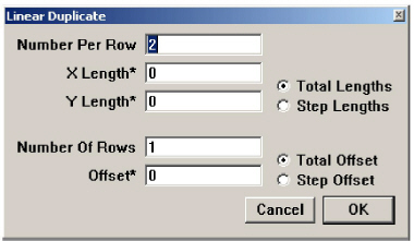
The Linear Duplicate dialog box contains the following settings:
|
Using the Linear Duplicate Tool
1. Select the object to be duplicated.
2. Choose Edit>Linear Duplicate or choose the tool from the Transform and Duplicate palette.
A dialog box appears.
An asterisk (*) appearing beside an entry field indicates that the field can be filled by dragging the mouse in the drawing area to indicate the length. This is a very handy and accurate way to specify this information.
3. Enter the Number of objects Per Row.
4. Specify Total or Step Lengths by clicking a button.
5. Click the X Length* data field.
6. Move the pointer to the drawing area and drag to indicate the length of the row of copies.
Both the X and Y values appear in the data fields.
7. If more than one row is desired, enter the Number of Rows, and click a button to specify the type of offset.
8. Enter the offset, if any. A negative number can be used.
Dragging to indicate the offset is particularly useful to equal the distance between two objects.
9. Click OK.
Suppose it is necessary to illustrate six machine screws. Draw the geometry, then use Linear Duplicate to copy the geometry in an array.
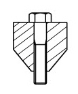
1. Create and select the geometry to duplicate.
2. Choose Edit>Linear Duplicate or choose the tool from the Transform and Duplicate palette.
3. Enter 6 in the Number Per Row data field.
4. Click the Step Length option.
5. Click in the X Length data field.
6. Move the pointer into the drawing area and drag across the widest point of the step.
7. Click at the end of the entry in the X Length data field.
8. Type *2 to multiply the width of the geometry by two.
9. Click OK.
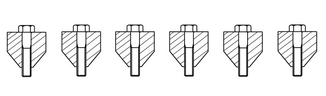
The geometry duplicates in a linear array.
Referral: For more information about using the Copy command in the Edit menu, see the section Editing Commands later in this chapter.

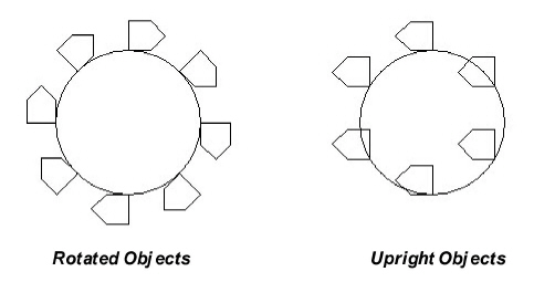
The Polar Duplicate command copies and rotates the selected geometry. When duplicating an object in a circular array, specify the number of duplications, the center of the array and whether the objects are copied in a rotated orientation or an upright orientation. In addition to the Transform & Duplicate palette, this tools is also accessed from the Edit menu.
Select this tool and the dialog box appears.
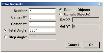
The Polar Duplicate dialog box contains the following settings:
|
Using the Polar Duplicate Tool
1. Select the object to be duplicated.
2. Choose Edit>Polar Duplicate or choose the tool from the Transformation palette
A dialog box appears.
An asterisk (*) beside an entry field indicates that the data can be filled in the field by dragging the mouse in the drawing area to indicate the length. This is a very handy and accurate way to specify this information.
3. Enter the Number of objects in the circular array.
4. Click the Center X* data field.
5. Move the pointer to the drawing area and click to indicate the center for the array of copies.
The values for Center X and Center Y appear in the data fields.
6. Specify Upright or Rotated objects by clicking a button. See the next section for the definition of these terms.
7. If Upright is specified, click a location for the reference point in the drawing area.
8. If the copies do not need to be in a complete circle, click the Total or Step Angle option.
9. Enter a value for the specified angle type.
10. Click OK.
To place a selected object three times in a semi-circle, enter 3 for the Number and 90° for the Step Angle.

The Copy by Path tool creates an array of copies along a curve. After selecting the object, anchor point and the path, the dialog box appears.
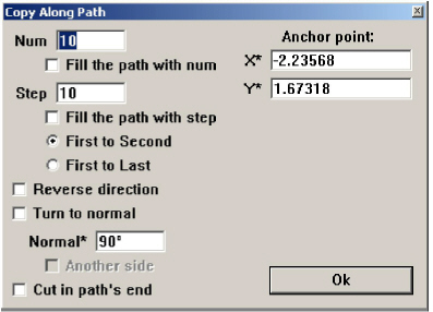
The Copy Along Path dialog box contains the following settings:
|
1. Choose the tool from Transformation palette.
2. Select the object to be duplicated.
3. Pick the anchor point.
4. Select the path (line, spline, circle...). Use SHIFT to choose several objects (rectangle, several splines...)
5. A dialog box appears.
6. Enter the Number of objects in the array.
7. Enter the Step.
8. Pick on the path to set start point.
9. Click the Complete set to continue working with this tool and start new array.

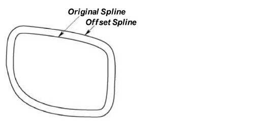
The Offset command creates offsets from lines, arcs, circles, ellipses and splines. In addition to the Transform & Duplicate palette, this is also accessed through the Edit menu.
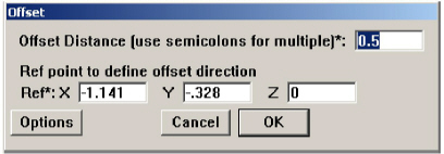
When selecting this command, the Offset dialog box appears.
The dialog box contains the following settings:
|
Clicking the Options button displays this dialog box.
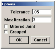
The Options dialog box contains the following settings:
|
1. Select the object to offset.
2. Choose Edit>Offset or choose the tool from the Transform and Duplicate tool palette.
The Offset dialog box displays.
3. Click into the Offset Distance* field.
4. Input an offset distance by dragging between any two points on the drawing area.
5. Click in one of the Ref* entry fields.
6. Enter an offset direction by dragging between any two points on the drawing area.
7. Click the Options button.
In the Options dialog box, specify a Tolerance, if needed, and whether or not the object will be offset with mitered corners.
The new geometry ungroups, and the original geometry remains selected.
For Graphite, if an offset is created with the work plane not set to match the plane of the object being offset, the results may be unpredictable. The Z* value is ignored in the Offset dialog box, and the distance is applied in the plane of the object being offset.
When an object is selected, move the pointer near the object until the 4-way Move symbol appears as shown below, and drag the object to a new location.

Note: If there is difficulty displaying the 4-way Move symbol, it might be because the Paste command was just used. When an object is drawn and then immediately copied and pasted, the original drawing tool is still in effect. Click the Selection tool to access the 4-way Move tool when the cursor is moved near an object.
Using the Drafting Assistant for Moving
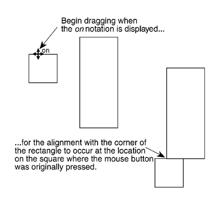
When the pointer becomes the 4-way Move symbol, drag the object around to see the Drafting Assistant’s notations relative to the object’s location. If the pointer is moved over a control point activated by the Drafting Assistant the object can be aligned using that point.
Selected Move versus Move Tool
Objects can be moved using either with the Selection tool or the Move tool, or nudged with the arrow keys.
Moving with the Selection Tool

The move tool of the Selection palette freely moves a selected object.
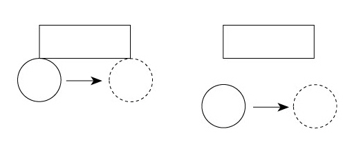
To move a circle from one location to another as shown above, use the Selection tool and the Drafting Assistant to align the 90° quadrant with the corner of the rectangle. The circles do not need to touch the rectangle to be aligned with it.
To move a circle or an arc from its center point, use the Move tool rather than the Selection tool.
Geometry can be nudged a specified distance within Graphite using the arrow keys on the keyboard.
1. Go to Layout>Preferences>Nudge or Right Mouse Click and choose Nudge.
1. Select an item or items to move or Nudge.
2. Use the arrow keys to move the selected items in the desired direction. By holding down the CONTROL key the nudge distance is doubled.

The Move tool relocates the selection with reference to other geometry.
Move a 1-inch square 2 inches in the X direction and 1 inch in the Y direction. See the following graphic.
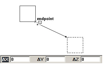
1. Select the square to be moved.
2. Select the Move tool.
Tip: Use the Move tool to move a circle or an arc by its center point. The Selection tool cannot do this.
3. Click one corner of the square when the endpoint notation displays.
4. Enter 2 in the X data field on the Status Line and -1 in the Y data field.
A positive or negative value entered in the Status Line determines the direction along the X or Y axis. A negative value moves the object to the left or down on the screen, and a positive value moves the object to the right or up.
5. Press the ENTER (Windows) or RETURN (Macintosh) key.
The square moves.
Moving Objects to Another Layer
1. Select the object(s) to move to another layer.
2. Choose Edit>Edit Objects.
3. In the Layer field of the Edit Objects dialog box select to the desired layer.
4. Click OK. The object is now located on the new layer.
Copy selections with the Copy command or by holding down the CTRL (Windows) or OPTION (Macintosh) key while using the following tools:
• Selection tool
• Single Line tool
• Center-Point and Opposite-Point Circle tools
• Ellipse tools
• Polygon tools
• Text tool
• Transformation tools
Copying with the Selection Tool
Hold down the CTRL (Windows) or OPTION (Macintosh) key and drag a copy of the selection to a new location.
1. Click the Selection tool.
2. Select the object(s) to copy.
3. Hold down the CTRL (Windows) or OPTION (Macintosh) key.
4. Drag a copy of the selection to a new location.
5. Release the CTRL (Windows) or OPTION (Macintosh) key.
Copying with the Geometry Tools
Make copies with the following drawing tools:
• Single Line tool
• Center-Point and Opposite-Point Circle tools
• Ellipse tools
• Polygon tools
• Text tool
1. Construct the geometry to copy.
2. With the drawing tool still activated, hold down the CTRL (Windows) or OPTION (Macintosh) key.
3. Click a new location. The click determines the location of the first point original geometry construction (the center of a center-point circle, for example).
4. Release the CTRL (Windows) or OPTION (Macintosh) key.
Copying with the Transformation Tools
Hold down the CTRL (Windows) or OPTION (Macintosh) key while using a Transformation tool to make a copy of the selected geometry.
1. Select the object to copy and transform.
2. Select one of the four Transformation tools.
3. Hold down the CTRL (Windows) or OPTION (Macintosh) key.
4. Perform the transformation according to the directions in the Message Line.
5. Release the CTRL (Windows) or OPTION (Macintosh) key.
A copy transforms and the original remains unchanged.
Copy Command versus CTRL (Windows) or
OPTION (Macintosh)
Usually, using the copy option of a geometry tool is faster than using the Copy and Paste commands in the Edit menu. The Copy command is very useful for copying to a different document or application.
Normally an object is sized with the Selection tool or the Expand/Shrink tool. In some cases it is possible to use the Move tool for sizing objects. Stretch objects by selecting a point and dragging it to a new location.
Referral: Sizing with the Expand/Shrink tool is described in an earlier section.
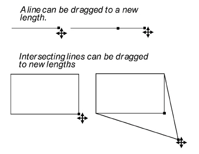
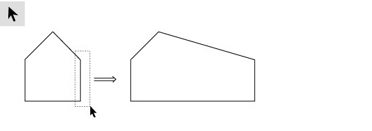
Sizing an Object with the Selection Tool
Stretch objects by selecting a point and dragging it to a new location.
1. In the Edit menu, be certain that Selectable Points is checked.
2. Click the Selection tool.
3. Drag a selection fence around the control points that represent the area to stretch.
4. Drag the points to a new location.
Sizing an Object with the Move Tool
Size an object with the Move tool. Using the Move tool allows the distance that selected point(s) should be moved to be specified by particular values along the X and Y direction in the Status Line.
To move the corner of the rectangle in the next graphic with the Move tool:
1. In the Edit menu, be certain that Selectable Points is checked.
2. Click the Selection tool.
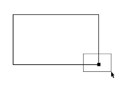
3. Drag a selection fence around the lower right corner of the rectangle, selecting only the point.
4. Click the Move tool.
5. Enter +1 in the X data field and -1 in the Y data field in the Status Line.
6. Press ENTER (Windows) or RETURN (Macintosh).
The corner of the rectangle moves the distance specified in the Status Line.
Use the Move tool for sizing objects only once since the next values entered in the Status Line do not refer to the new position of the moved point(s), but always to the original one. That means if (in our example) –1 is entered in the X data field and +1 in the Y data field, the point is not moved back to its original position, but in the opposite direction referring to its original position.
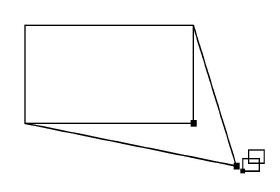
Selected Sizing Versus Expand/Shrink Tool
Dragging a control point of a selected object changes the size of the object, but it also distorts the object, changing the proportion between height and width.
The Expand/Shrink tool on the Transformation subpalette resizes geometry while maintaining its proportions.
In addition, specify proportions by clicking points on other geometry. For example, resize an object to fit within another object by clicking the boundary into which the resized object must fit.
Commands in the Edit menu select and manipulate objects. Two important commands in this menu are Undo and Redo which reverse an action or reinstate it. Four other commands in the Edit menu change objects without changing the physical geometry. Using them it is possible to copy or move objects within the same document, either on the same sheet or to other sheets. They are also used to copy or move objects to other documents, even to other applications.
The Cut, Copy and Paste commands do not alter the object’s attributes, such as the layer and pen style (color, weight, and pattern). To change the attributes of an object, choose Edit>Edit Objects. The Cut and Copy commands place a copy of the selected object on the Clipboard. The Clipboard is a buffer, a temporary storage place that holds the last cut or copied selection. The contents of the Clipboard are objects, not bitmaps or picts.
Tech Note: The difference between the Cut and Copy commands is that cutting a selection removes it from the drawing area while a copied selection remains in the drawing area.
CTRL+X (Windows); z+X (Macintosh)
The Cut command in the Edit menu removes the selected objects and places them on the Clipboard. Each selection cut or copied to the Clipboard replaces the previous Clipboard contents.
1. Select the object to be cut.
2. Choose Edit>Cut.
Once a selection is cut, it can be pasted. Use Cut and Paste to move geometry or text around the document, from one sheet to another, or from one document to another. Paste the cut selection onto a document in a different application.
Moving Geometry with the Cut Command
1. Select the objects to move.
2. Choose Edit>Cut.
3. Display the location for the selection to appear in the drawing area, scrolling if necessary.
4. Choose Edit>Paste.
The object appears in the center of the drawing area on the original layer on which it was created or onto the work layer if it’s from a different application. The object is selected so it can be moved.
Tip: To move an object from one layer to another, choose the Edit>Edit Objects
CTRL+C (Windows); z+C (Macintosh)
This command in the Edit menu places a copy of the selection onto the Clipboard without deleting the original selection. Paste the copy elsewhere in the current document or into a different document. Or even paste the copied selection into a document created with a different application.
Tip: It is also possible to create a copy of an object or text box with the Selection tool. First select the object, then hold down the CTRL (Windows) or the OPTION (Macintosh) key and drag a copy of the object to a new location.
Copy an object using any of the Transformation tools by holding down the CTRL (Windows) or the OPTION (Macintosh) key while using the tool.
1. Select the objects to be copied.
2. Choose Edit>Copy.
The selection goes on the Clipboard, and it remains in the current document.
CTRL+V (Windows); z+V (Macintosh)
The Paste command in the Edit menu pastes a copy of the Clipboard contents onto the center of the drawing area. The Clipboard contents are not changed when using the Paste command.
It is also possible to paste the selection into another Graphite document or into a document created with another application. To create an even distribution of geometry, in the Edit menu, use Linear Duplicate or Polar Duplicate.
1. If the object was cut or copied from a Graphite document, when it is pasted into another Graphite document it goes on the layer with the same name from which it was cut or copied. A pasted selection retains its original attributes.
Any geometry on a layer that is not in the new Graphite document is placed on the current work layer. So, make sure that the new document has all the layers of the pasted geometry by creating those corresponding layers in the new document before pasting the geometry.
2. Objects cut or copied from non-Graphite documents are pasted onto the work layer.
The Delete command in the Edit menu removes a selection without placing it onto the Clipboard. It is possible to Undo this deletion, but not Paste what is deleted. In addition to this command, use the DELETE (Windows and Macintosh) or BACKSPACE (Windows only) key to delete a selection. (Retrieve what was deleted with the Undo command).
CTRL+Z (Windows); z+Z (Macintosh)
This command in the Edit menu reverses the last action. For example, if an object is deleted, choose Undo to restore it. Then use Redo to return to the deleted version.
Undo affects actions that create and edit geometry and text, but not on actions that do not change the contents of the drawing, such as resizing the window or quitting.
When using a tool which involves a multi-step process, such as constructing with Connected Lines or creating a 3-Entity Fillet, choosing Undo reverts to the beginning of the process. Some other activities can be stopped by pressing the ESC key. The number of Undo commands is specified using Layout>Preferences>Undos.
CTRL+SHIFT+Z (Windows); No Key Command (Macintosh)
The Redo command in the Edit menu reinstates the last action reversed by Undo. Use Undo and Redo an unlimited number of times depending upon what is specified in the Preferences.
There are use several methods to erase objects:
• Select the object(s), then press the BACKSPACE (Windows) or DELETE (Macintosh) key. (Retrieve what was deleted with the Undo command).
• Select the object(s), then choose the Delete command from the Edit menu. (Retrieve what was deleted with the Undo command).
• Select the object(s), then choose Edit>Cut. (Retrieve what was cut by using the Paste command, as long as nothing else has been cut or copied.
Changing the Characteristics of Objects
Edit selected objects either by changing individual characteristics, such as weight or color, from the menu, or by changing the specifications in the Edit Objects dialog box.
The Edit Objects dialog box also provides information about the selected object in addition to allowing making changes.
CTRL+I (Windows); z+I (Macintosh)
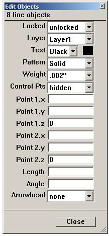
The Edit Objects command in the Edit menu changes the individual characteristics of selected objects, such as weight, layer, or pen style, or other specifications. Changes made through this dialog box are reversed with the Undo and Redo commands.
Tip: It is often faster to change a single geometric characteristic of an object by simply clicking the object and changing the geometry in the Status Line. But when changing several characteristics or attributes, it is better to use the Edit Objects dialog box.
1. Select the object to be edited.
2. Choose Edit>Edit Objects.
The dialog box appears.
3. Change the information in the data fields.
Click the data field, type a new entry and press ENTER (Windows) or RETURN (Macintosh). The object is modified instantly.
Many data fields have pop-up menus for selection. Press the down arrow and then drag to the selection desired. Once you click the option from the pop-up menu, the object is modified.
4. Click the Close button to close the Edit Objects dialog box.
Use Undo and Redo to reverse changes made through this dialog box.
Tip: Use the Expand/Shrink tool as well as the Edit Objects command to edit the measurements of existing objects. This dialog box is a fast, easy way to make several changes at once.
The specifications shown in the dialogue box depend on the type of object selected, and include at least the following:
• Number (or type) of objects
• Lock status
• Current layer
• Current color
• Current pattern
• Current weight
• Absolute coordinates for the starting point and ending point of the object
The measurements reflect the settings of the Units option in the Preferences submenu. To prevent changes to an object, specify locked in this dialog box, or select the object and choose Lock from the Arrange menu.
Tech Note: Use mathematical operators in the Edit Objects dialog box. A list of all allowed operators is in Appendix A: Operators and Units.
When doing a lot of editing, leave the Edit Objects dialog box displayed. That way it is possible to select the object, make the changes in the dialog box, click Apply, and then go on to the next object.
Tech Note: Use different units in each data field like inch (“), feet(‘), feet/inches (x’y”), centimeter (cm), millimeter (mm), or meter (m). It is possible to mix English and metric units as long as they are labeled correctly like 10” + 25.4 cm.
If more than one object is selected when Edit Objects is chosen, only the common information is displayed. Entries are blank when the information isn’t common. For example, if selecting two concentric circles, the center displays in the Edit Objects box but the diameter box is blank.
If several objects are selected and then Edit Objects is chosen, all of the objects reflect the changes made in the dialog box. For example, if all dimensions are selected and the text entry in the Edit Objects dialog box is changed to 2, all the dimensions display a 2.
Moving an Object to a Different Layer
1. Select the object(s) to be moved.
2. Choose Edit>Edit Objects.
3. Click the arrow for the Layer data field.
4. Click the layer from the list.
5. Choose Apply.
The Arrange menu contains commands that subdivide geometry, group geometry so it behaves like a unit, lock geometry to prevent changes and handle the draw order for objects. This menu also contains a command to refresh the screen after geometry have been changed.
This command in the Arrange menu subdivides the selected geometry into the specified number of equal parts.
1. Select the object to be divided.
2. Choose Arrange>Divide.
The dialog box appears.
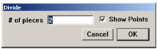
3. Enter the number of equal parts to divide the selection.
4. Click OK.
The divisions can be seen when displaying the points by clicking Show Points in this dialog box or choosing Layout>Show Points.
CTRL+Y (Windows); z+Y (Macintosh)
The Group command in the Arrange menu combines selected objects to function as a single object.
1. Select the objects to be grouped.
2. Select Arrange>Group.
Once geometry is grouped, the individual objects within the group can’t be edited unless ungrouped.
If the group is moved, all components move together. If the size of a group is changed, the individual objects change proportionally.
It is also possible to combine groups. For hierarchical groupings, Graphite ungroups each group in the order in which they were combined.
To create temporary groups, which are useful when moving multiple objects, drag a selection fence around several objects to treat them as a single unit while they are selected.
Changing the Members of a Group without Adding a Hierarchical Level
To add new geometry to an existing group, select the group and the new geometry and choose the Group command. This method creates a group within a group. To make a single group, follow these directions:
1. Select the group.
2. Choose Arrange>Ungroup. The geometry ungroups with the individual objects selected.
3. Hold down the SHIFT key and select the geometry to be added to the group.
4. Choose Arrange>Group.
Follow a similar procedure to remove members of a group.
The Ungroup command in the Arrange menu separates grouped objects into their individual components.
1. Select the group.
2. Choose Arrange>Ungroup.
The group becomes individual objects once again.
The Lock command in the Arrange menu prohibits editing or movement of selected geometry.
Preventing Accidental Changes to One or More Objects
1. Select the objects to be locked.
2. Choose Arrange>Lock.
Although moving or changing a locked object is not allowed, it is possible to copy, group, and select it.
Selected objects can also be locked or unlocked by clicking the locked box in the Edit Objects dialog box.
Preventing Changes to an Entire Document
1. Choose Edit>Select All.
2. Choose Arrange>Lock.
Selected objects can also be locked or unlocked by choosing the option in the Edit Objects dialog box.
The Unlock command in the Arrange menu removes the lock in the selection. Change and move the unlocked objects.
1. Select the locked object(s).
2. Choose Arrange>Unlock.
Selected objects can also be locked and unlocked by choosing the option in the Edit Objects dialog box.
CTRL+R (Windows); z+R (Macintosh)
The Redraw Screen command in the Arrange menu refreshes the screen. When changes are made to the constructions, the geometry may not be redrawn cleanly in the drawing area.
To redraw all of the geometry and remove extraneous artifacts, choose the Redraw Screen command from the Arrange menu.
Windows: Press the ESC or BREAK key to stop the redrawing of the screen. For interrupting long operations such as redraw, or linear or polar duplicate, use the BREAK key. If the operation was initiated by a control key command (such as CRTL+R for redraw) the ESC key is read by MS-Windows and it brings up a task list at the end of the operation.
Macintosh: Press ESC or the Command (z) key to stop the screen from redrawing.