Once objects have been constructed, they can be changed. One of the basic rules of Graphite says that an object should be selected before editing. Just as selecting a drawing tool from the tool palette before starting to draw, an object must first be selected before a function can be applied.
Modifying an object is always a two-step process:
1. Select the object.
2. Specify the action for the selected object.
For example, select a circle and then change the pen style to Center to indicate a bolt-hole circle.
The following topics are covered in this chapter:
• Objects
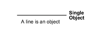
A single piece of geometry is an object.
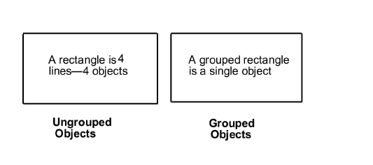
Several objects that have been grouped with the Group command are also an object.
For example, the four lines of a rectangle are four objects. By grouping them, Graphite treats them as a single object.
A point is an object, too. Every type of geometry contains two or more points, sometimes called control points. A line has two control points, one at the beginning and one at the end of the line. By selecting an object and choosing Layout>Show Points, the points are visible on the selected object.
Keep in mind, that an object must be selected first, followed by the command to execute a function.
Referral: Selecting points is described in a later section of this chapter.
By selecting a point without selecting the geometry it defines, Graphite treats the point as an object.
Upon selecting an object, its appearance on the screen shows that it is selected. It is a specific color (such as red), it blinks, or both. It is possible to change the color and turn blinking on and off for the selection indicator.
This command, found under Layout>Preferences, determines the appearance of selected objects.
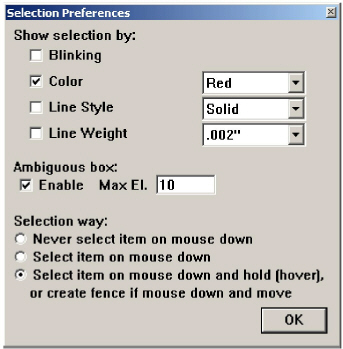
To choose a color, move the pointer to the color box and click on the color name to display the color list. Drag to the desired color and release or click the color. Once the selection color is changed, all current and future selected items appear in the new color.
Do not use black for indicating selection because many of the standard pens use black lines.
Selecting an object does not affect the properties of the object. A selected object highlights, but this highlighting goes away once the object is deselected. While points and objects are selected in a similar way, point selection is controlled by the Selectable Points setting in the Edit menu. For this reason, selecting objects and selecting points are discussed separately.
Graphite provides Selection tools and commands for selecting the objects.
There are five selection tools: Selection, Tracer, Select by Line, Select by Polygon and Eyedropper.
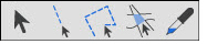

The Selection tool, in the first subpalette of the main tool palette, selects one or more objects or points in the drawing area.
1. Click the Selection tool in the tool palette. The Message Line reads, Select: Select [Shift = Extend, Ctrl = Copy (Windows) or Option = Copy (Macintosh)].

2. Move the pointer to an object and click. The object is selected, and any previously selected objects are deselected.
Selecting Multiple Objects Using the SHIFT key
1. Click the Selection tool in the tool palette.
2. Move the pointer to an object and click.
3. Press down the SHIFT key.
4. While holding down the SHIFT key, click other objects to be selected.
The objects clicked on are selected. Clicking one of the selected objects deselects it.
5. Release the SHIFT key.
Selecting Multiple Objects by Dragging
To select more than one object, drag a selection fence around the objects.
1. Click the Selection tool in the tool palette.
2. Drag a selection fence around the objects to select it.
All objects that lie completely inside the selection fence are selected. If a portion of an object is outside the region being dragged on, that geometry is not selected but the control points of the geometry which lie inside the selection fence are selected.
To select most of the objects within an area, drag a selection fence to select all the objects, and then deselect the objects by holding down the SHIFT key and clicking them.
Tip: Specify that only certain objects, layers, or colors are selected by setting a selection mask with the Selection Mask command. Select All is useful to make a global change in a drawing, such as changing the width of all lines.
Select all objects by double-clicking on the Selection tool.

This tool, in the first subpalette of the main tool palette, selects one or more objects along a straight line path when dragging a line over the desired objects.
1. Choose the Select by Line tool in the Selection tool palette. The Message Line reads, Select By Line: Draw line [Shift = Extend, Ctrl = Copy (Windows) or Option = Copy (Macintosh)].
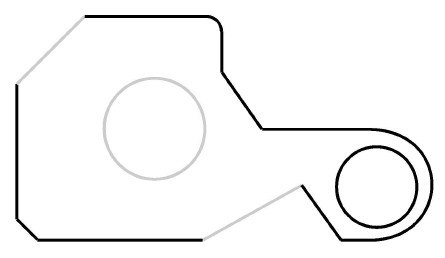
2. In the drawing area, drag across the objects you want to select, as shown in the graphic below.
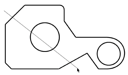
The objects intersected by the line are selected, as shown below in gray, and any previously selected objects are deselected.

This Tracer tool, in the first subpalette of the main tool palette, selects boundaries and uses coincident endpoints and line intersections to trace the perimeter of the geometry.
1. In the Selection tool subpalette, select the Tracer tool. The Message Line reads, Tracer: Pick curve to start trace. [Shift = Extend].
Tip: The Tracer tool is most useful for selecting boundaries for Crosshatching, Fills and for 2D Analysis because it eliminates the need to segment geometry.
2. Click on a boundary line.
The Tracer moves from one line to another making its selection.
With two overlapping objects as shown here, the Tracer tool selects the perimeter of the objects, depending on where the object is clicked.
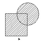
Clicking on the outside of the perimeter line, the Tracer tool selects the outer most perimeter.
The crosshatching of the figures below shows the boundaries selected when clicking the Tracer tool at the cursor locations shown.
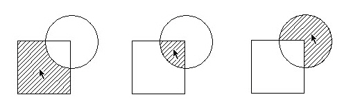
Clicking on the inside of the line, the tracer selects the inner most perimeter.
The Tracer tool does not select actual geometry, but rather creates temporary geometry that Graphite uses for operations like Fills, Crosshatching and 2D Analysis.
The Tracer tool does not work on a 3D model.

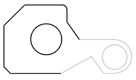
This tool, in the first subpalette of the main tool palette, selects one or more objects when a polygon is drawn around them. Each object must be completely enclosed by the selection polygon for the object to be selected. This tool functions similarly to the Connected Lines tool.
1. Choose the Select by Polygon tool in the Selection tool palette. The Message Line reads, Select By Polygon: draw polyline [Shift = Extend].

2. Click or drag to indicate the endpoints of the line segments that will make up this selection polygon. The selection polygon appears as line segments in the designated selection color.
Press the ESC key or choose Undo to remove the last line. Pressing the BACKSPACE key (Windows) or the DELETE key (Macintosh) removes the entire selection polygon.
3. Indicate the last point by double-clicking or choosing another tool.
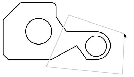
Completely enclose the object or objects to be selected. Objects not completely within the selection polygon are not selected. The graphic below shows the selected objects in gray.

The Eyedropper tool copies properties from a selected entity to another entity, including lines, fonts, layers or dimensions. For text the properties include font, size and color. For dimensions it includes text location, font, size, style, colors, line weight, layers and arrow head on/off.
1. Select the Eye Dropper tool from the Selection tools palette. The Message Line reads, Eye Dropper: Select objects to copy from [Shift=Extend].
2. Select or deselect multiple characteristics to be extracted for the Eye Dropper dialog box that automatically appears.
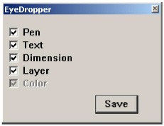
Click the Save button for the selections to be saved in Preferences and remembered each time the tool is selected.
3. Select the object with the characteristics to be copied.
4. Select the objects to receive characteristics. Apply the properties to multiple objects before clicking anywhere in open space to deactivate the tool.
Each object's characteristics change to those of the referenced object.
You can also select the object before you select the tool. If you do this, you only select the reference entity and the object automatically changes.
There are no Status Line entries.
To deselect an object, click anywhere in the drawing area where there is no object, or click any of the creation tools in the tool palette.
To deselect an object that was selected in a multiple selection operation. Hold down the SHIFT key and click the objects to deselect.
Graphite provides various selection commands for selecting objects.
CTRL+A (Windows); z+A (Macintosh)
This command in the Edit menu selects all objects except those on a hidden layer or excluded by the Selection Mask. Double-click the Selection tool to select all objects. By choosing Select All while using the Text tool, all characters in the current text area are selected.
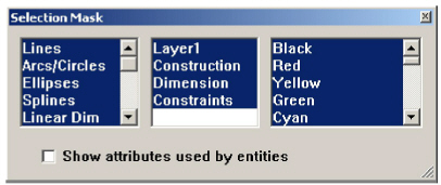
This command in the Edit menu limits selection by object type, layer and color. Only objects that are highlighted in the dialog box can be selected.
For example, if circles are not highlighted, when you choose Select All from the Edit menu, everything but the circles is selected. In this way, it is possible to select such combinations as only blue splines or only red objects on a particular layer.
Tip: The Selection Mask is useful to change particular groups of objects in a complex drawing. Use this feature to export some but not all geometry. Also use the Selection Mask to change all dimensions from parametric variables to real values as described in the Parametrics.
1. Choose Edit>Selection Mask.
The Selection Mask dialog box appears.
The highlighted items respond to all selection methods and are detected by the Drafting Assistant.
2. Designate the items allowed to be selected so they are highlighted.
While the dialog box is visible, it is possible to select, create and edit geometry. Move the dialog box if it covers geometry. The Selection Mask remains in effect after closing the dialog box until a tool is selected.
When an item in the dialog box is not highlighted, the Drafting Assistant and all the tools cannot detect it, even though it is visible on the screen.
Selecting or Deselecting Listed Items
• To select one item, simply click on the item and the rest of the list will be deselected.
• To deselect a list quickly, click one item in the list.
• To select a contiguous group of items, click on the item at the top or bottom of the desired group list, then hold down the SHIFT key and click or drag up or down to select the other items in the group.
• To select or deselect non-contiguous items, hold down the CTRL (Windows) or the z key (Macintosh) and click on the items.
The Selection Mask includes objects like lines, arcs/circles, text, etc. Most of the objects are self-explanatory except for those mentioned below.
|
Selecting points differs from selecting objects because points are not always visible.
Being able to select points is useful in two situations: stretching selected geometry (described later in this chapter) and control point selection for transformations.
When drawing a selection fence around objects, all geometry that is completely within the fence is selected. If geometry is partially within the fence, only the control points inside the fence are selected, and the geometry is not selected.
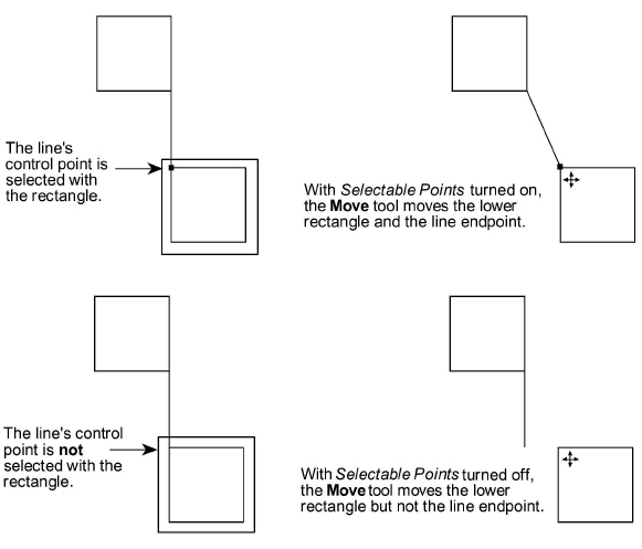
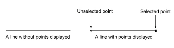
This command in the Layout menu toggles the display of the control points (endpoints, midpoints, center points, and knot points) for selected objects. When points are displayed, select a point by clicking it. If points are not displayed (but Selectable Points is set in the Edit menu), select a point by dragging a selection fence around the location of the point.
To show points for an individual selection, in the Edit menu, use the Edit Objects command.
By selecting and dragging an entire line, the line and the endpoints move. By selecting and dragging only an endpoint of the line, the endpoint moves and the line length changes while the other endpoint of the line remains fixed.
1. Select the geometry.
2. Choose Layout>Show/Hide Points to toggle the display of points on and off.
To turn off the point display once the points of an object are showing, select the object again and choose either Layout>Hide Points or the Control Points option in the Edit Objects dialog box.
Showing and Hiding Points with Stroke
When holding down the CTRL+SHIFT keys (Windows) or the Command (z) key (Macintosh) and clicking an object, the display of the object’s points toggles on or off. If the points are hidden when clicking the object, the points are displayed.
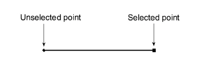
A control point can be selected whether the points are visible or not, however, Selectable Points in the Edit menu must be on, displaying a check mark in the menu. To select points if points are not visible:
1. Click the Selection tool.
2. Drag a selection fence around the location of the point.
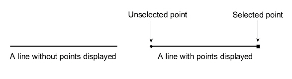
The selected point displays as a square.
To select points if they are visible:
1. Click the Selection tool.
2. Click the point.
The selected point displays as a square.
This command in the Edit menu selects points that aren’t displayed. When Selectable Points are not set, selecting points by dragging a fence is not possible. If points are displayed, simply click the point to select it. If points are not displayed, select a point by dragging a selection fence around it. The following example illustrates the use of Selectable Points.