


The process of moving from 2D to 3D geometry creation is relatively seamless. All of the tools used to create 2D geometry in Graphite are also used to create 3D geometry. However, there are some tools, features and concepts that are specific to 3D. The following topics are covered in this chapter:
Graphite tools behave in predictable ways in 3-dimensional space. Once you know the rules, manipulate the tools to construct the necessary geometry.
In traditional 3D computer-aided design, it is necessary to establish everything on work planes. It is as though a piece of glass has been propped on one of the faces of the model and you must draw on that plane. To work on a different plane, you must figuratively pick up the glass and carry it to the new position. With Graphite, it is possible to work freely within the model, using work planes or not as necessary. Move around inside the model and draw wherever desired. Generally, the only concern is the design, not moving the piece of glass.
The Drafting Assistant keeps tabs on the angles and intersections in all three dimensions. If geometry exists, draw relative to it. When it is simpler to use a work plane, or no geometry exists which is relative to the necessary plane, simply move Graphite's on-demand work plane with the Planes, 3-Point Plane and Define Plane commands in the 3D menu.
Referral: Work planes are discussed later in this chapter.
For example, to put a circle in the work plane or parallel to the work plane, it is possible to use tools which require only two specification points, such as the Center-Point Circle tool or the Opposite-Point Circle tool. To put a circle on a non-parallel plane, then use three-point specification tools, such as the 3-Point Circle tool or Tangent-Point Circle tool.
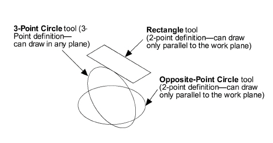
When a tool creates geometry from two points, the geometry lies on a plane parallel to the work plane. If the tool uses three points to define the geometry, the geometry will lie on the plane defined by the three points.
If the geometry does not specify three points (or two entities) in the necessary plane simply move the work plane.
Reminders:
There are two ways to see geometry in 3D:
• In the Views menu, choose Views and select a view. The default views are Isometric, Right, Front, Top and Trimetric.
• In the Views menu, choose Show Trackball. When the Trackball appears select a view from its own menu.
Three dimensional geometry is created or viewed using the Triad to display the orientation of the work plane on which the drawing is performed. The Show Triad command is located in the 3D menu. See Advanced Environment Settings for more information on the Trackball and the Triad.
Construction Rules for Tools Used in 3D
|
Graphite provides tools and features specific to the 3D environment.
This command, in the 3D menu, takes 2D geometry and makes it 3D through a simple extrusion process. There is also the option to extrude as a surface.
When you begin thinking about using this command, consider the following points:
• Which face shows the most detail?
• Will the extrusion be uniform or do some portions of the part have different dimensions?
For example, the top view of a bracket provides the most detail. Draw it with the Connected Lines tool on the tool palette.
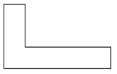
Once the basic shape is drawn, use the Extrude command from the 3D menu to create the depth of the bracket.
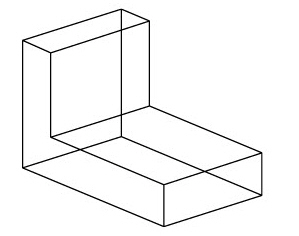
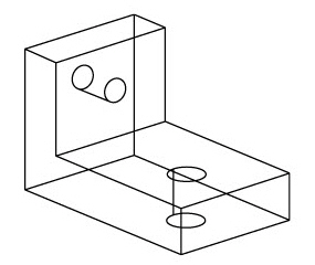
Once extruded, add some circles and extrude them to create holes in the bracket.
1. Draw the geometry to be extruded.
2. Select the geometry if it is not already selected.
3. Choose 3D>Extrude.
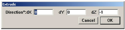
4. Enter the distance and direction or drag to specify the extrusion. Positive or negative values indicate the direction.
Use the Tab key to move between the x, y, and z coordinate data fields.
5. Click OK and the geometry is extruded.
Notes: X and Y are on the current work plane and Z is perpendicular to that plane. This is not necessarily relative to the original x, y, z axes that were used when the geometry was constructed.
If the object was drawn in the x,y plane, the extrusion should be in the z-direction. Therefore enter a z-value in the dialog box. Think of the screen as the 0 coordinate with positive values extending toward you and negative values away from you.
Manipulate the work plane to determine the direction of an extrusion.
The Revolve command, in the 3D menu, creates a model as though it were turned on a lathe. It copies and revolves a 2D object into a 3D object. There is the option to surface the geometry at the same time it is revolved.
Begin by drawing half of the model on an axis for revolving.
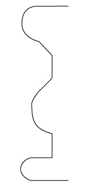
Then use the Revolve command to revolve the image a specified number of steps and angles.
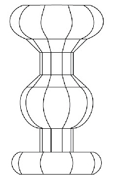
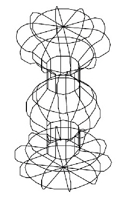
Finally, show the Trimetric view to see more detail of the wireframe.
1. Draw the geometry to be rotated.
2. Select the geometry if it is not already selected.
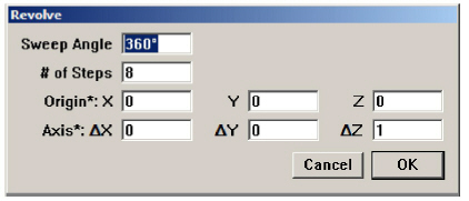
3. Choose 3D>Revolve. The Revolve dialog box displays.
Tip: Use the Tab key to move through the data fields.
4. Specify the number of degrees in the Sweep Angle for the revolution.
5. Specify the number of Steps (copies or divisions).
6. Tab to the Origin data field in the dialog box.
7. Place the target cursor at the startpoint of the axis of revolution.
Tip: To establish the axis of revolution, click the startpoint and the endpoint.
8. Drag along the axis from the startpoint to the endpoint. The six data fields are automatically filled in.
9. Click OK and the selected geometry is now revolved around the axis as specified, according to the right hand rule of revolution.
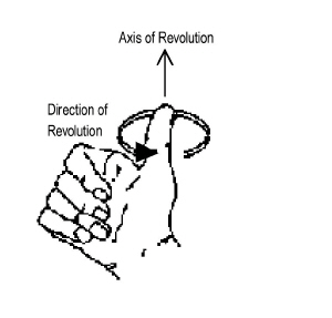
The direction of revolution is determined by the right-hand rule of revolution which states that if the thumb is pointed toward the positive axis of revolution, the revolution is in the same direction in which the fingers are curled.
Note: When revolving a circle that is eventually surfaced, the Axis of Revolution should be on an endpoint not a quadrant.
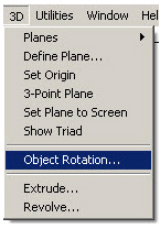
The Object Rotation command in the 3D menu, rotates geometry around any specified axis.
1. Select the geometry to rotate.
2. Choose 3D>Object Rotation.
3. In the Rotate Angle field, enter the angle to rotate the geometry.
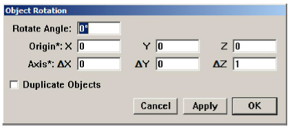
4. Tab to the Origin Data field. The cursor becomes a crosshair.
5. Click a point on the geometry to specify the Axis of Rotation around which to rotate the geometry.
6. Place the target cursor along the desired axis. Think of it as pointing to the top of a hinge.
7. Drag along the desired axis, as if dragging along the length of the hinge. Don’t worry about whether the z-axis is pointed in the right direction. The six data fields are automatically completed.
8. Click OK. The object rotates. Change the view as necessary to observe the change in rotation.
The Work Plane is the plane on which the geometry is created. It is an x, y plane with an origin of 0, 0, 0 for all data input. Move the work plane as desired by creating your own or choosing one of the standard work planes available in Graphite.
While learning to use Graphite, try to use the Drafting Assistant without moving the work plane. Even though the Drafting Assistant does a lot of the work, the work plane is still an essential element of 3D modeling.
The Z-Drafting Assistant assumes that geometry is being created in the current work plane unless it snaps to an align:z or to a logical snap point that is not in the current work plane.
Tech Note: If a work plane is named Temp Plane, it was created with the 3-point Plane command and will exist only for the duration of the current Graphite session. Rename the TempPlane work plane with the Define Plane command to make it a permanent plane for that file.
Also, there can only be one plane called Temp Plane in a document. If another plane is created using the 3-Point Plane command, without changing the name of the first, the new Temp Plane replaces the old one.
Creating the geometry that is not parallel to the current work plane and that does not snap to one of the Drafting Assistant’s constraints like endpoint or midpoint, and when using a tool that requires only two points for creation, such as the Center-Point Circle, Rectangle, or 2-Point Ellipse, use a work plane to place the geometry properly. Also, tools which use three points for specification can be drawn non-parallel to the work plane.
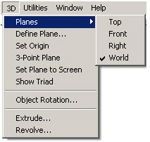
This command, in the 3D menu, displays the Planes submenu to set the current work plane. The standard work planes—Front, Right, Top and World—are always displayed, as well as any temporary plane generated (TempPlane) and any planes created with the Define Plane command. See margin notes.
1. Choose 3D>Planes.
The Planes submenu displays.
2. Drag down the submenu until the plane highlights.
3. Release the mouse button.
The work plane in the sheet view or active view window rotates as specified, and the work plane name is checked in the submenu.
Since only the plane is changed, the appearance of the geometry and its view orientation, remains unchanged. Therefore, it is possible to set the view to match the current work plane.
To move both the origin and change the orientation of the work plane, use either the 3-Point Plane command or the Define Plane command.
Specifying the Position of the Work Plane
In conventional CAD-programs it is necessary to specify both the orientation of the work plane and its exact location along the z-axis. In Graphite only the orientation of the work plane is specified. Once that is done, then all planes parallel to that orientation act equally as the current work plane, e.g. the Drafting Assistant identifies the location of the work plane automatically.
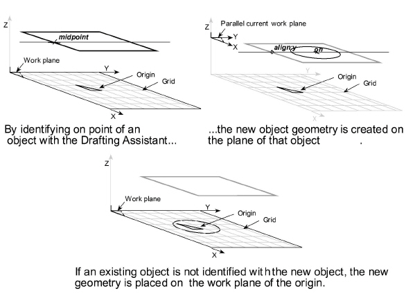
Another way to explain the relationship presented in the graphics above, is to remember the role of the Drafting Assistant. For new geometry to be placed on the same plane as another piece of geometry, brush over that existing geometry to wake up one of its control points like midpoint or endpoint. Graphite will then retain this plane information while creating the new geometry.
If no object exists or no geometry is referenced for plane information, Graphite places the new object geometry onto the work plane at the origin.
Occasionally, when working on a model, it may be necessary to move the origin of the work plane. This is especially useful for measuring distances. For example, open a document and start drawing without regard to the location of the origin, then move the origin to a convenient location for future reference.
Choose Layout>Show Grid to display the origin.
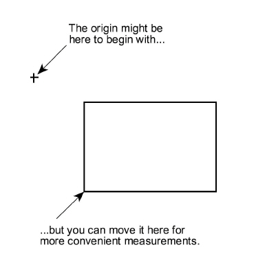
This command, in the 3D menu, sets a new origin in the current work plane.
1. Choose 3D>Set Origin.
2. Click in the drawing area to indicate the location for the new origin.
The origin of the current work plane is moved while the orientation of x,y,z remains the same.
To move the origin and change the orientation of the work plane, use either the 3-Point Plane command or the Define Plane command.
It is possible to define a work plane other than the standard planes. For example, to work on an angled face, reorient the work plane.
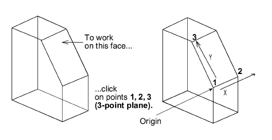
Define a new plane using two commands on the 3D menu, 3-Point Plane and Define Plane. To define a new work plane specify the origin and indicate the horizontal and vertical directions. Use 3-Point Plane to set the work plane, and then use Define Plane to name and save the plane.
This command, in the 3D menu, sets a temporary work plane from the three points specified. Follow the directions in the Message Line.
1. Choose 3D>3-Point Plane.
2. Click in the drawing area to indicate the point for the origin of the new work plane.
3. Click a point to define the positive x-axis.
4. Click a point to define the positive y-axis.
A temporary work plane is created and named TempPlane. The work plane moves, but the view does not change.
Rename this plane by going to the 3D menu and choosing Define Plane. There is an option to Rename in the dialog box. See a later section for more information. If the new plane is not renamed, it is replaced by the next specified 3-Point Plane and removed from the list when exiting Graphite.
This command, in the 3D menu, defines a new work plane, names a temporary plane or changes a standard plane. The standard planes cannot be changed unless the lock icon is clicked off. Their default configurations are defined as follows:
|
When changing any of the standard planes, always revert to the world plane to return to the original orientation.
Having used other CAD applications, you may be familiar with the terms World Coordinate System and User Coordinate System. The World Coordinate System is equivalent to Graphite’s world work plane and the User Coordinate System is equivalent to the current work plane.
1. Choose 3D>Define Plane.
The Define Plane dialog box displays.
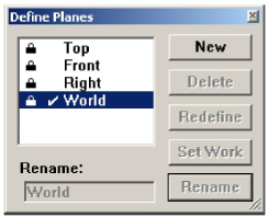
2. Click New.
The Redefine Plane dialog box displays and the Origin data field highlights.

The new work plane is named Plane 1 by default.
3. On the drawing area, click the location for the new origin.
The Right data field is selected.
4. Click a location on the positive x-axis.
The Up data field is selected.
5. Click a location on the positive y-axis.
6. Click OK.
The definition box goes away and the new plane is defined. The new work plane is named Plane 1 by default. If this plane is not renamed, the next plane created will be Plane 2.
7. Select Plane 1, the new plane just created.
8. Click Set Work.
The current plane changes to the new specification.
9. Rename this work plane if desire.
10. Dismiss the dialog box if it is no longer needed to define other work planes.
Be aware that simply changing the work plane does not mean that work done is on the visible face. The view orientation must be adjusted accordingly.
1. Choose 3D>Define Plane.
2. If necessary, click the lock icon to unlock the plane, then click the plane to be renamed in the list box.
3. Type a new name.
4. Click Rename.
The plane is renamed. If the renamed plane was a temporary plane, it becomes permanent. The name is added to the Planes submenu and the list in the Define Plane dialog box.
The World plane cannot be renamed.
1. Choose 3D>Define Plane.
2. If necessary, click the lock icon to unlock the plane and then click the plane to be deleted from the plane list.
3. Click Delete.
A plane cannot be deleted if it is set as the current work plane. First make another plane the current work plane and then it can be deleted.
To delete a standard plane (Front, Right, or Top), unlock it. World plane cannot be deleted. To delete a standard plane, do not choose Save Preferences. In this case, the plane must be recreated for use in future files.
Use Define Plane to change the origin or orientation of the axes of any plane, except the World plane.
1. Choose 3D>Define Plane.
2. Click the lock icon on the plane to be changed.
3. Click the name of the plane to change it.
4. Click Redefine.
The Redefine Plane dialog box displays the settings as they appear on the screen with the origin selected.
5. On the drawing area, click the location for the new origin.
The Right data field is selected.
6. Click a location on the positive x-axis.
The Up data field is selected.
7. Click a location for the positive y-axis.
8. Click OK.
The plane is redefined.
The standard work planes—Front, Right, and Top—cannot be redefined without unlocking them. The World plane, which was established from the original orientation of the model, cannot be redefined.
This command, in the 3D menu, sets the work plane to be coincident with the screen, where the origin is in the center of the screen; the x-axis is coincident with the width of the screen and the y-axis is coincident with the height of the screen.
This sets the plane to match the screen in all views which is particularly useful when moving from view to view while drafting.
To name this work plane, use the Define Plane command.