


This chapter describes how to create geometric objects that are the building blocks for the designs created with Graphite's drawing tools. It also describes how the Drafting Assistant makes design faster and easier. The following topics are contained in this chapter:
Referral: For more information about the Drafting Assistant, see The Drafting Assistant.
• Drawing Tools - Description and Use
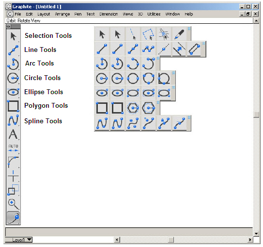
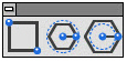
Drawing begins with the tool palette, located at the left of the Ashlar-Vellum Graphite drawing area shown below:
The tool palette has seven subpalettes of tools used to create and select geometric objects. These seven tools are the drawing tools.
Most drawing tools offer two methods for creating an object: clicking and dragging.
|
Both methods are available in most tools.
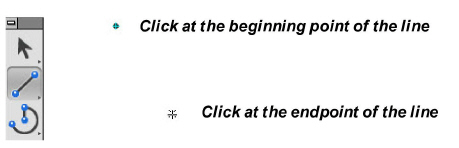
To make object creation easier, Graphite's tools contain a feature called Smart Pointers. While working with a tool, the tool icon shows the points that must be indicated to create an object with the tool.

Each dot on the icon, such as the Single Line tool icon shown here, represents a point to place either by clicking or by dragging. The smart pointer indicates the order for designating points while drawing the geometry.
1. Select the Single Line tool from the tool palette.

2. Move the pointer to the drawing area and click to set the starting point of the line.
3. Move the pointer to the desired location for the endpoint of the line and click.
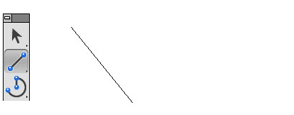
Tech Note: Notice that there is no rubberband guide line when using the clicking method.
The line is drawn between the two points.
Immediately after construction, changes can be made in the Status Line at the bottom of the drawing area to alter the length or position of the line. If the geometry isn’t satisfactory, just press the BACKSPACE (Windows) or the DELETE (Macintosh) key.
1. Click the Single Line tool in the tool palette.
2. Move the pointer into the drawing area.
3. Press and hold the mouse at the desired location for the starting point of the line.
4. With the mouse button still held, move the mouse to the desired location for the endpoint of the line.
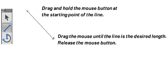
Tip: Notice that when dragging between points, a rubberband line acts as a guide. When using the clicking method, unrelated activities, such as zooming can be performed between clicks.
5. Release the mouse button to set the endpoint.
Immediately after construction, changes can be made in the Status Line at the bottom of the drawing area to alter the length or position of the line. If the geometry is not satisfactory, just press the BACKSPACE (Windows) or the DELETE (Macintosh) key.
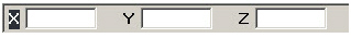
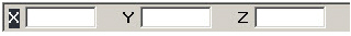
Whenever a tool from the tool palette is selected, the Status Line appears along the bottom of the drawing area. It contains fields that provide information about the current construction. For example, when the Single Line tool or Connected Lines tool is the current tool, the Status Line contains fields for the X, Y and Z coordinates of the beginning point and the change of X, Y and Z values for the endpoint of the line. It also contains the value of the length and angle of the line.

Use the Status Line in three ways:
• To create an object with keyboard entries only.
• To edit an object that was just created and is still selected.
• To create an additional object using the current tool.
When constructing an object, the status field contains selected specifications that can be changed (the field is highlighted). For example, when drawing a line with the Single Line tool, the Length data field is highlighted to enter a value for the length. Just type a value. Press ENTER (Windows) or RETURN (Macintosh) and the line is redrawn at the new length.
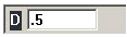
Set the number of decimal places for the Status data field entries or fractional round off by going to Layout>Preferences>Units. In the Units dialog box set the precision.
To make an entry in a different status field, use one of four selection methods:
• Press the Tab key to cycle the selection highlight through the status fields from left to right.
• Click inside the status field and the pointer becomes an I-beam text cursor.
• Double-click inside the status field to select the entire contents of the field.
• Click the field label to select the entire contents of the field.
Tip: Notice how each method affects the selection of the contents of the status field. Clicking once inside the field places the cursor where clicked. If double-clicking inside the field, the entire entry is selected for editing.
Using the Status Line with Drawing Tools
After an object is drawn, specifications, such as the length, angle and location can be adjusted in the Status Line. It is possible to make these changes immediately, before constructing another object, selecting a different tool, or choosing another command.
Make only one series of changes in the Status Line (in as many fields as necessary). After pressing ENTER (Windows) or RETURN (Macintosh) Graphite redraws the object to the specifications. Once ENTER (Windows) or RETURN (Macintosh) is pressed, make subsequent changes with the Edit Objects command in the Edit menu.
Note: When working in English units, values in the Status Line can be entered as a combination of feet and inches. Enter them as x'y" and not x'-y". The dash reads as a minus sign and x'-y" is calculated as an equation. See Appendix A for operators and units.
Try the following exercises to create and change a single line with the Status Line.
Altering Geometry in Progress with Status Fields
1. Select the Single Line tool.
2. Click two locations in the drawing area. The length (L) field automatically highlights in the Status Line.
3. Type 3. The 3 is entered directly in the L field.
4. Press the Tab key to select the next status field. The angle (A) field now highlights.
5. Enter 15.
6. Press ENTER (Windows) or RETURN (Macintosh).
Pressing ENTER (Windows) or RETURN (Macintosh) completes the data entry for this object. The line redraws 3 units long and at a 15° angle.
Remember that by pressing ENTER (Windows) or RETURN (Macintosh), Graphite constructs the object based on the specifications in the status fields. Pressing ENTER (Windows) or RETURN (Macintosh) a second time in the above example creates a second line with the same values. Since the lines have the same values, the second line overlays the first line, obscuring it from view.
Creating Additional Geometry with Status Fields
1. With the Single Line tool still selected from the previous example, click two more points.
2. Type 4.
3. Press the Tab key and type 25.
4. Press ENTER (Windows) or RETURN (Macintosh). Another line is drawn.
Creating New Geometry with Status Fields
1. Choose the Selection tool so the Single Line status field clears.
2. Click the Single Line tool again.
With the X status field is active, enter a value for the X coordinate of the beginning point of the line.
3. Type 0.
Note: Do not press ENTER (Windows) or RETURN (Macintosh) until step #10.
4. Press the Tab key. The Y field highlights.
5. Type 0.
6. Press the Tab key again.
The dX field highlights. The dX value is the delta X, the numeric difference between the beginning and ending X coordinate.
7. Type 2.
8. Press the Tab key. The dY field highlights.
9. Type 2.
10. Press ENTER (Windows) or RETURN (Macintosh). The line is drawn.
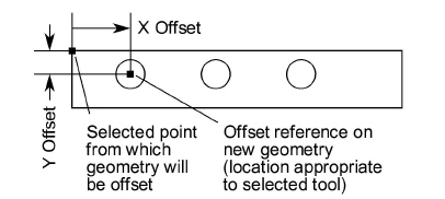
Creating Geometry Offset from a Point
To create geometry that is offset from an existing point, use the Status Line to specify the offset.
1. Select the tool.
2. Move the pointer over the control point from which you want the offset.
3. Click once to lock onto that point.
4. Click in the appropriate X or Y field in the Status Line, placing the text cursor at the end of the entry.
5. Type the offset (such as + 3") and press ENTER (Windows) or RETURN (Macintosh).
6. Continue the construction.
The Message Line is an important feature when drawing. Upon selection of a drawing tool, the line displays the tool selected and the first step in its use. Following each step, the line displays the next one until the steps are completed. The Message Line may also display additional commands to use with the tool. See the example below.
Drawing Tools - Description and Use
This section describes the drawing tools found in the tool palette. For a description of the selection tools see Selecting Objects.
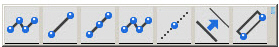
The Line tools in the Line tool palette create line segments, connected lines, lines parallel to existing lines and smart walls. While creating a line, the coordinate locations, line length and angle from horizontal appear in the Status Line. Dragging creates a rubberband smart wall, so that it is seen before it is drawn. The line is also drawn with the current pen specifications for color, weight and pattern.

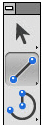
This tool, in the second subpalette of the main tool palette, draws a line between two points. Click or drag to draw a line.
1. Select the tool. The Message Line reads, Single Line: Pick the beginning point. [Ctrl = Copy previous (Windows) or Option = Copy previous (Macintosh)].
2. Click two endpoints of the line,
or
Drag to indicate the endpoints of the line; press at the beginning and release at the end of the line. While dragging, a rubberband line previews the construction.
To copy the line just created, as the Message Line indicates, hold down the CTRL (Windows) or OPTION (Macintosh) key and click once in the drawing area. A line appears that is identical to the one just drawn. The location of the click designates the location of the first endpoint.
The Status Line specifies the X,Y and Z coordinates of the beginning, the relative location of the end (delta X, delta Y and delta Z), the line length, and the angle from horizontal. Once a line is drawn, the line Length is the selected status field.

Drawing a Line Perpendicular to Another Object
1. Construct the object.
2. Move the pointer to the object until a Drafting Assistant on notation appears. The Drafting Assistant notation must be on rather than endpoint, quadrant, or midpoint.
3. Drag straight away from the object in a perpendicular direction. A perpendicular line appears attached to the object. Keep holding the mouse down and move the cursor. Notice that the line stays perpendicular but slides along the object.
4. Drag to the desired length for the perpendicular line.
Drawing a Line Tangent to or Perpendicular to a Curve
1. Construct an arc, circle, or ellipse.
2. Choose the Single Line tool.
3. Move the pointer to the arc until a Drafting Assistant on notation appears. The Drafting Assistant notation must be on rather than endpoint, quadrant, or midpoint.
4. Drag in the appropriate direction (straight for perpendicular or at an angle for tangent) until the Drafting Assistant perpendicular or tangent notation appears.
5. When the Drafting Assistant locks on to perpendicular or tangent, drag the line around the arc to the desired location and extend the line to the necessary length.
Create a point by creating a line and setting its length to zero. Set the starting point of the line with the mouse, then type 0 in the Length entry field of the Status Line and press ENTER (Windows) or RETURN (Macintosh). The line (“point”) displays a + to indicate its location. A 0 length line can also be created by clicking the Single Line tool twice in the same spot.

This tool, in the second subpalette of the main tool palette, creates a line that starts from the center and dynamically draws in both directions until the endpoint is clicked.
1. Select the tool. The Message Line reads, Mid-Point Line: Pick center point. The message guides each successive step.
2. Click to indicate where the mid-point of the line will be.
3. Indicate one end point and the line grows symmetrically in the opposite direction.

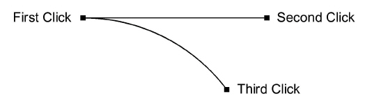
This tool, in the second subpalette of the main tool palette, draws lines in which the endpoint of one line segment is the beginning point of the next.
Using the Connected Lines Tool
1. Select the tool. The Message Line reads, Connected Lines: Pick the beginning point. The Message Line guides each successive step.
2. Indicate the endpoints of the line segments.
If you click a point and then change your mind, press the ESC key, or choose Undo to remove the last line. Pressing the BACKSPACE (Windows) or DELETE (Macintosh) key removes all connected lines in the current construction.
3. Indicate the last point by double-clicking or by choosing another tool.
After completing at least one segment with the Connected Lines tool, it is possible to create a tangent arc off of the last line by holding down the CTRL (Windows) or the OPTION (Macintosh) key (the pointer temporarily changes to an “arc” icon) and clicking or dragging to the next point. The Message Line notes this added feature. Several tangent arcs can be strung together by continuing to hold down the CTRL (Windows) or OPTION (Macintosh) key. (Note: The radius of these arcs cannot be edited with this method.)
The Status Line specifies the X,Y and Z coordinates of the beginning, the relative location of the end (delta X, delta Y and delta Z), the line length and the angle from horizontal. Once the line segment is created, line Length is the selected status field. By entering successive sets of data and hitting ENTER (Windows) or RETURN (Macintosh) after each set, a continuous string of connected lines can be entered from the keyboard.


This tool, in the second subpalette of the main tool palette, constructs lines that help while drawing. Classic construction lines are always relative to the zoom level at which they are created. Infinite construction lines pay no attention to zoom level and are infinite in any direction. The construction line is infinite if the Layout>Preferences>Infinite Construction Lines option is checked. If the same option is unchecked, the dotted line appears limited by the endpoints clicked with the mouse while creating it. Use the following methods for creating construction lines:
Using the Construction Lines Tool
1. Select the tool. The Message Line reads, Construction Line: Pick beginning point. The Message Line guides each successive step.
2. Click in the drawing area to specify the point through which the construction line should go.
3. Click once again with the mouse button indication the another point through which the construction line must go.
The Status Line has the fields with the coordinates of the last construction line drawn. You can change the data in the Status Line fields and the line coordinates will change accordingly.

Referral: For more information on construction lines see also Permanent Construction Lines

This tool, in the second subpalette of the main tool palette, constructs lines parallel to existing lines. Use one of the following methods for creating parallel lines:
1. Select the tool. The Message Line reads, Parallel Lines: Drag new line off existing line. The Message Line guides each successive step.
2. Indicate the line to duplicate then drag to the new position. Enter the delta distance in the Status Line and press ENTER (Windows) or RETURN (Macintosh).
or
Click the line to duplicate then enter a delta distance in the Status Line and then press ENTER (Windows) or RETURN (Macintosh). (This method does not allow control of which side of the original line the new line is drawn.)
The status field specifies the distance between the original line and the new parallel line.
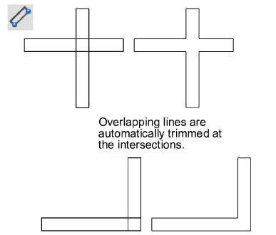
The Smart Wall tool, in the second subpalette of the main tool palette, constructs a double line like those used in architectural drawings. Please note: this tool functions correctly only in the Top view. Results are not accurate if drawn in any other view.
This tool works in much the same way as the Single Line tool except that it draws double lines or walls. Walls created on the same layer automatically trim to where they touch or intersect. Automatic trimming of smart walls occurs only when the walls are on the same layer. Dragging creates a rubberband smart wall, so that it is seen before it is drawn.
Tip: To use the Smart Wall feature for single lines, create the lines with the Smart Wall tool and enter 0 for the thickness of the wall.
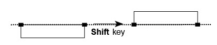
When dragging the mouse, the defining side of the wall falls on the construction line dragged along. The other side of the wall automatically fills in at the thickness specified in the Status Line. The position of the automatic wall depends on the last activity. If the second wall is on the wrong side of the construction line, press the SHIFT key to flip it. Notice the Message Line reads “Shift = Flip” as a reminder of this feature.
To fillet or chamfer or otherwise alter a Smart Wall layout, first ungroup them with the Ungroup command in the Arrange menu. The result is that the selected Smart Walls turn into separate line segments and the “smarts” are stripped out. This cannot be undone. Regrouping the pieces will not make them Smart Walls again. It is recommended to place all symbols before ungrouping and filleting/chamfering the walls.
1. Select the tool. The Message Line reads, Double Line: Pick start point. [Shift = Flip]. The Message Line guides each successive step.
2. In the Status Line, specify the thickness (T) of the wall.
3. Indicate the ends of the wall segment.
Press the SHIFT key to flip the wall to the opposite side.
4. Continue specifying both endpoints for wall segments, as needed.
After deleting a merged segment, the remaining walls redraw.
The Status Line specifies the thickness of the wall, the X,Y coordinates of the beginning point, the wall length and the angle from horizontal. Once the wall segment is created, wall Length is the selected status field.

Parametric symbols (like door and window symbols) can be constructed in a way that automatically cuts an opening in the Smart Wall on which they are placed. Examples of this are included with Graphite in the Architect library within the Symbols folder. When moving the symbol along the wall to another position, the wall automatically closes at the old position and the opening appears at the new position.
1. The symbol must contain a Smart Wall piece that is thicker than the wall segment on which it will be placed.
2. Set the pen pattern of the smart wall piece to dotted. (Any geometry in a symbol that is of the dotted pen pattern is placed on the drawing, but it is invisible.) This results in an invisible Smart Wall piece that cuts the Smart Walls on the drawing.
Parametrics works with Smart Wall configurations, but it can be tricky. While using parametrics, turn on the point display (Layout>Show Points) and hook dimension objects right to the displayed points rather than to the lines. Keep in mind that double walls obscure the fact that smart walls are actually single lines.
For more information on parametrics, see Parametrics.
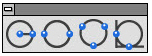
Use the Arc tools to create an arc by any of three methods:
• Center-Point
• 3-Point
• Tangent Point
When creating each arc, the Status Line displays entries such as coordinate locations, radius, angle from horizontal and delta angle. Dragging creates a rubberband ellipse, so the ellipse is seen before it is drawn.
The arc is drawn with the current pen specifications for color, weight and pattern.
Note: After an arc is created, move it as desired by the center point, when the arc is selected.

This tool, in the third subpalette of the main tool palette, draws an arc from three points: the center point, arc beginning point and arc endpoint.
Using the Center-Point Arc Tool
1. Select the tool. The Message Line reads, Center-Point Arc: Pick center. [Ctrl = Copy previous (Windows) or Option = Copy previous (Macintosh)]. The Message Line guides each successive step.
2. Indicate the center point of the arc.
3. Indicate the radius and beginning of the arc.
All three points can be clicked, but the rubberhand arc doesn’t appear with this method. To construct an arc greater than 180°, drag rather than click, the endpoint.
The Status Line specifies the X,Y coordinates of the center of the arc, the length of the radius, the starting angle from horizontal and the delta angle from the start. Radius is the selected status field.

Note: After an arc is created, move it as desired by the center point, when the arc is selected.

This tool, in the third subpalette of the main tool palette, draws an arc through the points selected.
1. Select the tool. The Message Line reads, 3-Point Arc: Pick first point. [Ctrl = Tangent to object (Windows) or Option = Tangent to object (Macintosh)].
2. Indicate the first endpoint of the arc.
3. Indicate the second and third positions.
The arc is drawn from the first position designated, through the second position, and ends at the third position.
Clicking on a separate object while holding down the CTRL (Windows) or OPTION (Macintosh) key, the arc is drawn tangent to the specified object rather than through the exact click-point. For each of the three clicks that define the arc, if the CTRL (Windows) or the OPTION (Macintosh) key is held down and the cursor is placed on some other object, Graphite will define the arc to be tangent to that object at the nearest tangency point. If the CTRL (Windows) or OPTION (Macintosh) key is not held down, then the arc is created directly through that exact point. Each of the three points is treated separately.
The Status Line indicates the X,Y coordinates for each of the three points.

Note: After an arc is created, move it as desired by the center point, when the arc is selected.

This tool, in the third subpalette of the main tool palette, draws an arc beginning at the first point specified. The second point specified is the direction vector and the third point indicates the endpoint of the arc. Essentially, the Tangent-Point Arc tool first creates a line, then creates an arc tangent to the line, then erases the line.
Using the Tangent-Point Arc Tool
1. Select the tool. The Message Line reads, Tangent-Point Arc: Pick beginning point of arc (tangent line). The Message Line guides each successive step.
2. Indicate the starting point. This is both the starting point of the arc and the starting point of the temporary tangent line.
3. Indicate the endpoint of the tangent line.
4. Indicate the endpoint of the arc. The arc is drawn between the first and last point clicked and tangent to the line between the first and second points.
The Status Line specifies the X,Y coordinates of the endpoints of the arc and the angle of the tangent line.

Note: After an arc is created, move it as desired by the center point, when the arc is selected.
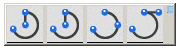
The Circle tools on the tool palette construct circles by any of four methods:
• Center-Point
• Opposite-Point
• 3-Point
• Tangent
Center-Point uses the center and diameter of the circle. Opposite-Point uses the diameter. 3-Point uses three points and can be tangent to existing objects. Tangent-Point draws a circle tangent to two objects, using the diameter specified. Dragging creates a rubberband ellipse, so the ellipse is seen before it is drawn.The circle is drawn with the current pen specifications for Color, Weight and Pattern.
Tech Note: A Circle Center Line tool is available for creating axis dimensions. For more information, see Dimensions.
Note: After a circle is created, move it as desired by the center point, when the circle is selected.

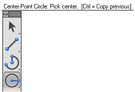
This tool, in the fourth subpalette of the main tool palette, draws a circle specified by the center point and diameter.
Using the Center-Point Circle Tool
1. Select the tool. The Message Line reads, Center-Point Circle: Pick center. [Ctrl = Copy previous (Windows) or Option = Copy previous (Macintosh)].
2. Indicate two locations; the first click places the center and the second determines the radius.
3. To create a copy of the last circle, hold down the CTRL (Windows) or OPTION (Macintosh) key and click once in the center for the new circle.
The Status Line shows the X,Y coordinates of the center and the diameter of the circle. Diameter is the selected status field.

Note: After a circle is created, move it as desired by the center point, when the circle is selected.

This tool, in the fourth subpalette of the main tool palette, draws a circle specified by the diameter.
Using the Opposite-Point Circle Tool
1. Select the tool. The Message Line reads, Opposite-Point Circle: Pick first point on circle. [Ctrl = Copy previous (Windows) or Option = Copy previous (Macintosh)]. The Message Line guides each successive step.
2. Indicate two locations for the diameter,
Create a copy of the last circle drawn by holding down the CTRL (Windows) or the OPTION (Macintosh) key and clicking once to place first point of the new circle.
The Status Line specifies the X,Y coordinates representing the endpoints of the diameter.

Note: After a circle is created, move it as desired by the center point, when the circle is selected.

This tool, in the fourth subpalette of the main tool palette, draws a circle through the points selected.
1. Select the tool. The Message Line reads, 3-Point Circle: Pick first point. [Ctrl = Tangent to object (Windows) or Option = Tangent to object (Macintosh)]. The Message Line guides each successive step.
2. Indicate the first point on the circle.
3. Indicate the second and third points.
If any of the three points are placed on an existing object, the circle is drawn through that point. By clicking an object while holding down the CTRL (Windows) or OPTION (Macintosh) key, the circle is drawn tangent to the object rather than through the indicated point. Combine the placement of these points to create a circle through a specific point of one object and tangent to another object, or a circle tangent to three objects, or any other combination.
The Status Line indicates the X,Y coordinates for each of the three points.

Note: After a circle is created, move it as desired by the center point, when the circle is selected.

This tool, in the fourth subpalette of the main tool palette, draws a circle tangent to the two objects indicated.
1. Select the tool. The Message Line reads, Tangent Circle: Enter diameter then pick first tangent object. The Message Line guides each successive step.
2. Enter a diameter for the circle in the status field.
3. Click the objects to which the circle is to be tangent.
Note: After a circle is created, move it as desired by the center point, when the circle is selected.
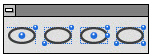
The Ellipse tools on the tool palette construct ellipses inscribed within an invisible rectangle or parallelogram by any of four methods:
• 2-Point Center
• Opposite-Corner
• 3-Point Center
• 3-Corner
The 2-Point Center Ellipse uses the center point and one corner location of the rectangle. The Opposite-Corner Ellipse uses opposite corners of a rectangle. The 3-Point Center Ellipse uses the center point, the midpoint of a side and the corner of the parallelogram. The 3-Corner Ellipse uses three corners on a parallelogram. Click or drag to create the ellipse. Dragging creates a rubberband ellipse, so the ellipse is seen before it is drawn.
The ellipse is drawn with the current pen specifications for Color, Weight and Pattern.
Ellipses do not have center points by design. By drawing lines between opposite vertex points on the ellipse, the intersection of the two lines is the center of the ellipse. For a 2-Point Center Ellipse (inscribed in a rectangle) the Drafting Assistant's horizontal and vertical temporary construction lines will cross at the center point once two vertex points are touched.
Note: After an ellipse is created, move it as desired by the center point, when the ellipse is selected.

This tool, in the fifth subpalette of the main tool palette, constructs an ellipse inscribed within the rectangle calculated from the two specified points: the center point and one corner of the rectangle.
Using the 2-Point Center Ellipse Tool
1. Select the tool. The Message Line reads, 2-Point Center Ellipse: Pick center of ellipse. [Ctrl = Copy previous (Windows) or Option = Copy previous (Macintosh)]. The Message Line guides successive steps.
2. Indicate the center of the ellipse.
3. Indicate the corner of the rectangle defining the ellipse.
If the two points are on the vertical or horizontal axis, a straight line is drawn.
To create a copy of the last ellipse, hold down the CTRL (Windows) or the OPTION (Macintosh) key and click in the center of the future ellipse.
The Status Line specifies the X,Y coordinates of the center point and the length and angle of the semi-major and semi-minor axes of the ellipse.

Note: After an ellipse is created, move it as desired by the center point, when the ellipse is selected.

This tool, in the fifth subpalette of the main tool palette, draws an ellipse inscribed in the rectangle specified by the opposite corners indicated.
Using the Opposite-Corner Ellipse Tool
1. Select the tool. The Message Line reads, Opposite-Corner Ellipse: Pick first corner of rectangle. [Ctrl = Copy previous (Windows) or Option = Copy previous (Macintosh)]. The Message Line guides successive steps.
2. Indicate one corner of the rectangle defining the ellipse.
3. Indicate the opposite corner of the defining rectangle.
If the two points are on the vertical or horizontal axis, a straight line is drawn.
To create a copy of the last ellipse, hold down the CTRL (Windows) or the OPTION (Macintosh) key and click the lower-left point of the future ellipse.
The Status Line allows specifying the X,Y coordinates of the lower-left point and the length and angle of the major and minor axes of the ellipse.

Note: After an ellipse is created, move it as desired by the center point, when the ellipse is selected.

This tool, in the fifth subpalette of the main tool palette, constructs an ellipse inscribed within the parallelogram calculated from three specified points: the center point, the midpoint of a side and a corner of the parallelogram.
Using the 3-Point Center Ellipse Tool
1. Select the tool. The Message Line reads, 3-Point Center Ellipse: Pick center of the ellipse. [Ctrl = Copy previous (Windows) or Option = Copy previous (Macintosh)]. The Message Line guides successive steps.
2. Indicate the center of the ellipse.
3. Indicate the midpoint of the side of the rectangle defining the ellipse.
4. Indicate the corner of the rectangle defining the ellipse.
If the three points are on the vertical or horizontal axis, a straight line is drawn.
To create a copy of the last ellipse, hold down the CTRL (Windows) or the OPTION (Macintosh) key and click where the center of the future ellipse.
The Status Line specifies the X,Y coordinates of the center point and the length and angle of the sides of the parallelogram.

Note: After an ellipse is created, move it as desired by the center point, when the ellipse is selected.

This tool, in the fifth subpalette of the main tool palette, draws an ellipse inscribed in the parallelogram calculated from the three corners specified.
Using the 3-Corner Ellipse Tool
1. Select the tool. The Message Line reads, 3-Corner Ellipse: Pick first corner of control parallelogram. [Ctrl = Copy previous (Windows) or Option = Copy previous (Macintosh)]. The Message Line guides through each successive step.
2. Indicate one corner of the parallelogram defining the ellipse.
3. Indicate another corner of the defining parallelogram.
4. Indicate the final corner of the defining parallelogram.
If the three points are on the vertical or horizontal axis, a straight line is drawn.
To create a copy of the last ellipse, hold down the CTRL (Windows) or the OPTION (Macintosh) key and click where the lower-left corner of the future parallelogram.
The Status Line specifies the X,Y coordinates of a corner and the length and angle of the sides of the parallelogram.

Note: After an ellipse is created, move it as desired by the center point, when the ellipse is selected.
These tools on the tool palette draw rectangles, inscribed polygons or circumscribed polygons. They create lines which are individual objects. To treat a polygon as a single object, select all lines of the polygon and choose the Group command in the Arrange menu.
Dragging to indicate the points of the polygon creates a rubberband image. The polygon is drawn with the current pen specifications for Color, Weight and Pattern.

This tool, in the sixth subpalette of the main tool palette, draws a horizontal or vertical rectangle, using the opposite corners specified.
1. Select the tool. The Message Line reads, Rectangle: Pick first corner of rectangle. [Ctrl = Copy previous (Windows) or Option = Copy previous (Macintosh)].
2. Indicate the opposite corners of the rectangle,
Create a square by aligning the second point on the 45° construction line. If the two points are on the vertical or horizontal axis, a straight line is drawn. To draw a square from the center rather than opposite corners, use one of the other polygon tools, specifying four sides. It is not possible to create a rectangle from the center.
Changing the Width and the Height of a rectangle in Edit Objects dialog box is not possible. Each line must be edited individually because rectangles become four line objects after deselecting the rectangle.
Create a copy of the last rectangle by holding down the CTRL (Windows) or the OPTION (Macintosh) key and clicking where to place the upper-left corner of the future rectangle.
A default 1-inch rectangle is drawn if a rectangle has not been previously drawn.
The Status Line specifies the X,Y coordinates of the first point, as well as the width and height of the rectangle. Width is the selected status field.


This tool, in the sixth subpalette of the main tool palette, draws a regular polygon where the radius of the circumscribing circle determines the location of the polygon’s vertices.
The default polygon is a hexagon, but specifying the number of sides is possible in the Status Line. The Status Line shows a diameter for the circle, the standard way of describing a polygon inscribed in a circle.
Using the Inscribed Polygon Tool
1. Select the tool. The Message Line reads, Inscribed Polygon: Pick center of polygon. [Ctrl = Copy previous (Windows) or Option = Copy previous (Macintosh)]. The Message Line guides successive steps.
2. Indicate the center of the polygon.
3. Indicate a point on the circumference of the circumscribing circle.
Create a copy of the last inscribed polygon by holding down the CTRL (Windows) or OPTION (Macintosh) key and clicking where you want the center.
The Status Line specifies the X,Y coordinates of the center, the diameter of the circle defining the polygon, and the number of sides. Diameter is the default Status Line selection, and the default number of sides is six.


This tool, in the sixth subpalette of the main tool palette, draws a regular polygon for which the radius of the circle determines the midpoint of the sides. The default shape is a hexagon, but it is possible to specify the number of sides in the Status Line. (Note: The Status Line shows a diameter for the circle, the standard way of describing a polygon circumscribed around a circle.)
Using the Circumscribed Polygon Tool
1. Select the tool. The Message Line reads, Circumscribed Polygon: Pick center of polygon. [Ctrl = Copy previous (Windows) or Option = Copy previous (Macintosh)]. The Message Line guides successive steps.
2. Indicate the center of the polygon and the midpoint of one of the sides
Create a copy of the last circumscribed polygon by holding down the CTRL (Windows) or OPTION (Macintosh) key and clicking where you want the center.
The Status Line specifies the X,Y coordinates of the center, the diameter of the circle defining the polygon, and the number of sides. The default number of sides is six. Diameter is the default Status Line selection.

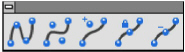
The spline tools on the tool palette create NURBS (Non-Uniform Rational B-Splines) which are a superset of Bezier curves. These splines are curves created by a complex mathematical formula.
NURB splines provide designers with two interrelated functions. First, curvature continuity remains intact when the curve is changed. Kinks don't develop as the spline is altered. Second, NURB splines provide localized control of a complex curve. Isolate an area and make changes without affecting the remainder of the spline.
These properties are essential in aerodynamic designs. Air molecules moving over a wing surface must flow smoothly for maximum aero-dynamic lift. If the surface does not maintain curvature continuity, the air molecules separate from the wing surface and cause a vacuum. Such a vacuum causes an eddy as the molecules try to fill it. This disruption of air flow increases the drag, which is not a part of an effective design.
The automotive industry needs smooth air flow to improve gas mileage. Complete curvature continuity also improves styling. The appearance of a car is one of the major sales factors. The potential buyer would not be impressed if the showroom lights’ reflection on the car rippled and wavered. It is complete curvature continuity that makes a smooth reflection.
Localized control of complex curves allows minor modifications to be made without adversely affecting the shape. For example, if a new, bigger engine doesn’t fit under a perfectly-designed hood, use a NURB spline to raise the center of the hood without changing the basic design.
NURB splines are also valuable for injection mold designs to eliminate the swirl of plastic as it is injected into the mold. Such designs provide better surface finishes and allow thinner cross-sections in the die.

The Through-Points Spline tool, in the seventh subpalette of the main tool palette, draws a spline through the points placed
.
Using the Through-Points Spline Tool
1. Select the tool. The Message Line reads, Through-Points Spline: Pick control point (Double-click last point).
2. Indicate the points for the vectors of the spline.
3. Double-click the last point.
The Status Line shows the X,Y, and Z coordinates of each point along the path. (Graphite shows only X and Y coordinates.)
If a spline crosses over itself, the Drafting Assistant will not be able to find that intersection. This is by design.

This tool, in the seventh subpalette of the main tool palette, draws a spline using vectors determined by the points specified. The Vector Spline tool uses each point placed as the vertex of a vector for the spline it creates.
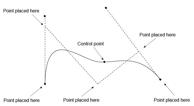
1. Select the tool. The Message Line reads, Vector Spline: Pick control point (Double-click last point).
2. Click the points for the vectors of the spline.
3. Double-click the last point.
Graphite uses these vectors to calculate the control points (two fewer than the number of vertices specified). The spline is tangent to the first and last vectors and passes through the calculated control points.
The Status Line shows the X,Y, and Z coordinates of each point along the path.

This tool, in the seventh subpalette of the main tool palette, adds another control point to an existing spline.
Using the Add Spline Control Point Tool
1. Select the tool. The Message Line reads, Add Spline Control Point: Pick location on spline.
2. Click on the spline at the desired location(s) for the new control point(s).
Note: To see the new control point(s), as well as the existing control points, first select the spline and then choose Layout>Show Points (or use the Edit Objects dialog box to specify display points).
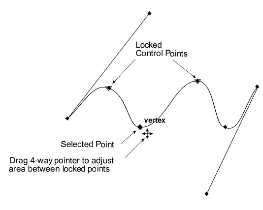
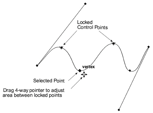
To move a point, be sure to lock the adjacent points so you don’t change the slope of the rest of the spline.
Lock Spline Control Point Tool

This tool, in the seventh subpalette of the main tool palette, locks specified points on an existing spline so that the slope between the points can be changed without affecting the rest of the spline.
Tech Note: The Lock command in the Arrange menu is used to prevent changes to objects and doesn’t affect spline control points.
Using the Lock Spline Control Point Tool
1. Select the spline.
2. Choose Layout>Show Points.
3. Select the tool. The Message Line reads, Lock Spline Control Point: Pick control point.
4. Click the vertices to lock.The Lock Spline Control Point tool is used to lock or immobilize selected control points on an existing spline. Then adjust the curvature of the spline between the locked points without disturbing other areas of the spline.
Unlocking Spline Control Points
1. Select the tool and click on the point to unlock it.
Locking More than One Spline Control Point
1. Lock more than one point by simply clicking each point.
Editing Control Points of a Spline
1. Select the spline with the Selection tool.
2. Choose Layout>Show Points. (If the menu says Hide Points, no need to choose it.)
3. Click on the drawing area to deselect the spline.
4. If necessary, select the Lock Spline Control Points tool from the Spline tool subpalette.
5. If necessary, click the points to lock (the points on either side of the point to be changed).
6. Use the Selection tool to select the point to change.
7. Drag the point to the new location.
The dotted lines that appear tangent to the end portions of the spline are tangent control arms. They adjust the curvature of the spline leading up to the endpoints without moving the endpoints themselves. To do this, select the endpoint of the tangent control arm and drag it to another location with the 4-way pointer that appears.
Editing the End Slope of a Spline
1. Select the spline with the Selection tool.
2. Choose Layout>Show Points. (If the menu says Hide Points, no need to choose it.)
3. Click in the drawing area to deselect the spline.
4. If necessary, select the Lock Spline Control Points tool from the Spline tool subpalette.
5. If necessary, select the point to lock but not the endpoint.
6. Use the Selection tool to select the point at the end of the tangent control arm that needs to be moved.
7. Drag the point to a new location.
It is not possible to move both endpoints of a spline at the same time. Select and move the endpoints individually.