


The Drafting Assistant makes Graphite unique among design and drafting software products. The Drafting Assistant thinks like a drafter; it automatically knows where construction lines are typically wanted and temporarily displays them when needed.
The Drafting Assistant also makes it easy to select existing points for construction by displaying information about the pointer’s location in the drawing area. If a Drafting Assistant notation displays when clicking, the construction snaps onto the geometry precisely, without requiring finely tuned eye-hand coordination or tedious selection of special modifiers, modes, or other specialized construction tools.
The following topics are covered in this chapter:
• Drafting Assistant Construction Lines
• Permanent Construction Lines
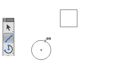
When the pointer is in the drawing area, it has a snap point function. The snap point locks onto specific points on existing objects as the pointer moves near them.
|
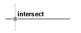
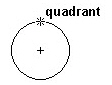
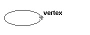
The Drafting Assistant tells when the snap point is on an object.
It displays information about the location of the snap point. This information appears either beside the pointer or next to the object itself.
|
The Drafting Assistant tells when the snap point has locked onto the points of an object as follows:
|

Using Tangents and Perpendiculars
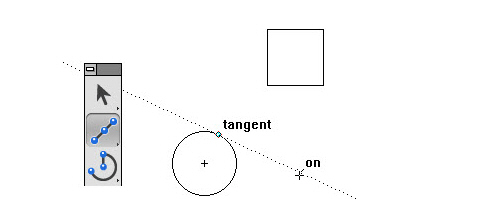
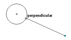
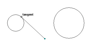
By clicking a point on an arc or circle and dragging the pointer away at about a 45º angle, the Drafting Assistant locks onto the tangent. If you drag away at a 90º angle the Drafting Assistant locks onto a perpendicular.
|
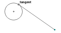
Continue holding the mouse button, and the line remains tangent or perpendicular while dragging the ending point around the object.
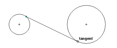
This is a useful feature if, for example, it is necessary to create a line from the tangent on an existing circle to the tangent point of another circle.
Once a line is tangent to the circle, it can be dragged to the tangent point on the other circle, with the tangency maintained at both ends.
The Drafting Assistant locks onto a tangent or perpendicular only when the Drafting Assistant starts from the on notation. It is not possible to begin a tangent or perpendicular line from a specific point, such as endpoint, quadrant or vertex.
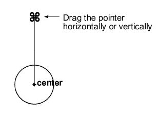
It is possible to direct the Drafting Assistant to snap onto an object. For example, to start a new line from the exact center of a circle. Hold down the mouse button and press the C key on the keyboard. The Drafting Assistant finds the center of the circle when moving the pointer near the center.
Tech Note: Another way to create geometry from an exact location relative to another object is to reduce the Hit Radius of the Drafting Assistant with a lower number of pixels or to zoom in on the drawing to separate the construction points visually.
Using the Drafting Assistant for Snapping onto Geometry
The following table lists the keys for finding specific points. The desired point must be within the Hit Radius (defined later in this chapter) of the pointer. Press the mouse button first and then press one of the following keys on the keyboard.
Keyboard snap points only work when there are multiple snap points within the Hit Radius of the pointer.
|
Pressing the SPACEBAR or clicking the mouse releases all snap restrictions.
Keyboard snap points act as a filter. For example, to place the end of a line at the center of a circle where the intersection of two other objects lies near the center (within the specified Hit Radius), the Drafting Assistant does not know which point—the center or the intersection—to snap to. By pressing the C on the keyboard while dragging the line, the Drafting Assistant knows to snap to center and to disregard the intersection (or any other snap point that falls within the Hit Radius).
This command, found in Layout>Preferences, turns the Drafting Assistant on or off. When the Drafting Assistant is not checked in the menu, the Drafting Assistant is off.
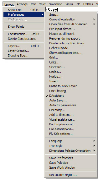
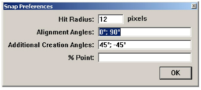
This Snap command, found in Layout>Preferences, sets specifications for the Drafting Assistant.
|
The Snap command is available by going to Edit>Snaps Filter. This command activates and deactivates the different snap modes of the Drafting Assistant. This command is different from the Snap command, chosen through the Layout>Preferences menu, that sets basic specifications of the Drafting Assistant.
Choosing Edit>Snaps Filter displays the following dialog box:
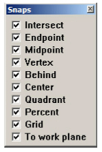
All snap modes are activated by default. To deactivate a snap mode click the related check box.
Drafting Assistant Construction Lines
In addition to snapping to geometry, the Drafting Assistant also displays dynamic construction lines. Three types of construction lines are used most frequently: vertical, horizontal, and 45° angle lines. These display automatically during construction. Construction lines appear temporarily to help align geometry. Once a point is set, the Drafting Assistant construction line disappears so that the drawing is not cluttered with extraneous lines.
Dynamic construction lines extend automatically from the last point created. To activate other points so the Drafting Assistant displays construction lines relative to them, simply move the pointer over the geometry to activate or “wake-up” its control points, then move away horizontally or vertically.
Of course, there is the option of creating permanent construction lines and other shapes, as described later in this chapter.
Using the Drafting Assistant’s Construction Lines
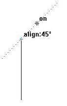
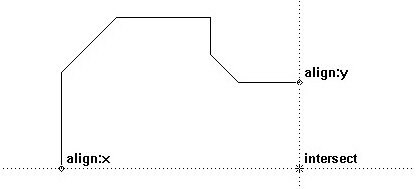
Indicate the first endpoint of a line and move the pointer horizontally, vertically, or in a 45° direction, the dynamic construction lines appear. The figure here illustrates a 45° construction line relative to the endpoint of an existing line.
Displaying Dynamic Construction Lines while Constructing Geometry
1. Click a point to begin new geometry.
2. Move the pointer away from the point horizontally, vertically, or at a 45° angle.
3. While the construction line is visible and the Drafting Assistant displays on, click the next point.
The point is placed exactly on the construction line, even though the pointer wasn’t exactly on that line when clicked. The dynamic construction line disappears.
Displaying Dynamic Construction Lines with Existing Geometry
1. Without pressing the mouse button, move the pointer over an existing point.
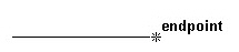
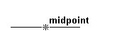
The point notation (endpoint or midpoint, for example) shows that the point is active.
2. Move the pointer horizontally or vertically.
A construction line appears through the point.
3. While the construction line is visible and the Drafting Assistant displays on, click the desired point in the construction.
The point is placed exactly on the construction line, even though the pointer wasn’t exactly on that line when clicked. The dynamic construction line disappears.
The figure here illustrates intersecting construction lines drawn through two existing, active points.
Once familiar with the Drafting Assistant, Graphite will streamline design and drafting tasks.
Tech Note: Up to eight active points are available. Activating the ninth point in a series deactivates the first point.
Setting New Drafting Assistant Construction Angles
Add to or change the angles that the Drafting Assistant uses for dynamic construction lines by choosing Layout>Preferences>Snap. Enter the construction line angles, separated by semicolons, in the appropriate data field.
In addition to the Drafting Assistant’s dynamic construction lines, it is possible to create construction lines that display until hidden or removed. There are three methods for creating permanent construction lines: strokes, with the Construction Line tool and the Construction command in the Layout menu. Construction lines automatically appear on the construction layer, not the work layer of the drawing. Hide the construction layer to view or print the drawing without construction lines.
To remove all construction lines, choose Layout>Delete Constructions. Everything on the construction layer deletes, regardless of the object's pen style.
Referral: For using the Construction Line tool see Construction Lines Tool.
Referral: More information on Layers is found in Viewing Geometry.
Stroke construction lines are lines that are created with the mouse. Hold down the CTRL+SHIFT keys (Windows) or the z key (Macintosh) and drag the mouse horizontally or vertically. The Drafting Assistant helps to place the stroke precisely.
Holding down the CTRL+SHIFT keys (Windows) or the z key (Macintosh) changes the mouse pointer to the Stroke point (z).
|
Tip: Use strokes to create construction lines while you are in the process of using another tool.
Using Stroke Construction Lines
Construction lines are as long as the dimensions of the viewing area of the screen or the plot region (as designated in Drawing Size dialog box in the Layout menu), whichever is larger.
For example, if using the Connected Lines tool to create a construction line that extends through the center of a circle:
1. Hold down the CTRL+SHIFT keys (Windows) or the z key (Macintosh). The pointer becomes the Stroke pointer (z).
2. Move the pointer near the center of the circle.
The Drafting Assistant snaps onto the center point.
3. Drag the mouse vertically or horizontally away from the midpoint.
The construction line appears through the center while still in the process of creating connected lines. Releasing the CTRL+SHIFT keys (Windows) or the z key (Macintosh) and continue working.
Stroke construction lines are useful for creating lines through existing points. To create a construction line at a location other than an existing point or at a particular angle, use the Construction command.
Using the Command CTRL+K (Windows) z+K (Macintosh)
This command in the Layout menu creates a construction line on the construction layer of the document.
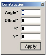
Specify the angle of the construction line or the offset from a reference point defined by the X, Y coordinates. The asterisk shows that the values are specified by clicking or dragging the mouse. Values are also typed into the data fields.
The distance dragged is always entered in the Offset data field as a positive value, regardless of the direction dragged.
Any geometry placed on the Construction layer will not have a Midpoint snap. This is by design so that construction data will not confuse the user’s work area. It is not advisable to create a drawing on the Construction layer because there is no Midpoint snap and because the Layout>Delete Construction will delete all geometry on this layer. The Construction layer is really used for Graphite to store construction line data and should not be used for regular geometry.
Tech Note: Graphite automatically places construction lines on the construction layer. When choosing Layout>Delete Constructions, everything on the construction layer is deleted, regardless of the object’s pen style.
Specifying the Construction Line Angle with the Mouse
1. Click the Angle data field.
2. Drag a vector in the drawing area.
The angle of the vector line appears in the Angle data field.
Specifying the Construction Line Offset with the Mouse
1. Click the Offset data field.
2. Drag the offset distance in the drawing area.
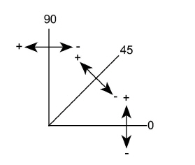
The distance dragged appears in the Offset data field. The offset is determined by the angle of the construction line as shown.
Specifying X,Y Coordinates with the Mouse
The coordinates of the last point specified appear in the X and Y data fields. To change them, do the following:
1. Click the X data field.
2. Enter new coordinates, or
In the drawing area, click the location of the point through which the construction line will pass. The coordinates are entered automatically for the X and Y data fields.
Creating Multiple Construction Lines
Create multiple construction lines through the same point by entering the angles separated by semicolons.
Creating Parallel Construction Lines
Create parallel construction lines by specifying a single angle value with different offsets separated by semicolons. It is also possible to create parallel lines by creating one construction line using this data field, then creating new lines with the Parallel Lines tool.
Creating Construction Geometry
Non-construction geometry is placed on the work layer. Create temporary construction geometry, such as arcs or circles, by making the construction layer the work layer, creating the construction geometry and then switching to another layer to continue working.
Use the Construction pen style if desired, but it’s not essential.
Lines made with the Construction pen do not go on the construction layer unless that layer is the work layer.
Creating Construction Geometry
1. Choose Layout>Layers.
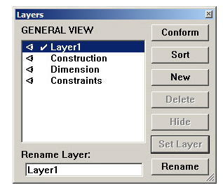
2. Click Construction in the list box.
3. Click Set Layer.
4. Create the geometry for construction. Use the Construction pen style if desired.
5. When the construction geometry is complete, make another layer the work layer.
6. Close the dialog box.
7. Continue to work.
Once the construction geometry is no longer needed, choose Layout>Delete Constructions to remove all geometry on the construction layer.
Tip: Select construction lines in the usual manner from any layer. The construction layer doesn’t have to be the work layer.
To delete only one or two construction lines among many, select the lines to remove, and then choose Edit>Delete or press the BACKSPACE (Windows) or DELETE (Macintosh) key. To remove all the construction lines created, choose Layout>Delete Constructions.
This command in the Layout menu deletes all construction lines and any geometry on the construction layer. The Drafting Assistant’s dynamic construction lines appear only temporarily and are not affected by this command. Any geometry on the construction layer (regardless of the pen style used) is deleted by this command.
Retrieving the deleted construction geometry is possible with the Undo command.