


The Basics
This chapter describes the basic components of Graphite. This brief overview of useful features may be all you need to know if you are familiar with CAD software. The following topics are covered:
• Parts of the Graphite Window
• Menu Bar, including the Dialog Boxes
For more information about standard elements such as menus, scroll bars, File menu commands, and dialog boxes, refer to the Windows or Macintosh User’s Guide that came with your computer.
Tips: If you are left-handed and your mouse has more than one button, you can change the functionality to the right mouse button. Make this change in the Control Panel of Windows.
The mouse is your communication device to tell the computer what to do. Use the mouse to indicate locations, choose commands, select tools, and construct objects.
If your mouse has more than one button, use the right button to popup a menu that contains a variety of commands and functions. By default the right mouse button provides shortcuts to the most popularly used commands.
To set up the right mouse button options, right click in the drawing area to activate the menu. Choose RightMouse. When the dialog box appears, check the boxes to activate or deactivate items displayed in the popup menu. If your mouse has three buttons or a scroll wheel, click and hold the button or wheel to pan. Move the scroll wheel forward and back to zoom in and out.
Tip: If holding down the middle button does not pan, then the button has been defined as something else by the operating system and can be changed in the Control Panel or System Preferences.
This manual uses the following terms for mouse activities:
|

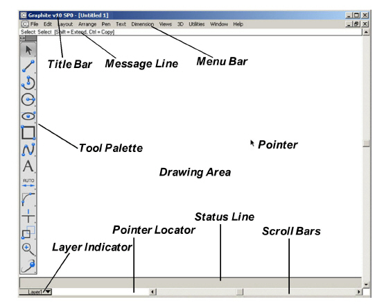
Upon starting Graphite, the following window appears.
|
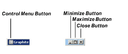
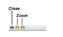
The Title Bar includes the name of the current document, and the Control Menu, Minimize and Maximize/Restore buttons (Windows), or the Close and Zoom boxes (Macintosh).
|
|
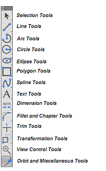
A tool palette is a group of tool icons along the left side of the screen. The icons represent the tools for drawing, editing, and annotating geometry.
Selecting a Tool from the Tool Palette
1. Position the arrow pointer on the icon of the desired tool.
2. Click the mouse button.
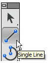
The icon highlights to indicate its selection. The Single Line tool is selected here.
Most of the tools in the tool palette contain a subpalette with related functions. The arrow in the lower-right corner of the tool icon indicates the presence of a subpalette.
Viewing and selecting from a subpalette are similar to choosing a command from a menu.
Selecting a Tool from a Subpalette
1. Position the arrow pointer on the tool.
2. Press the mouse button.
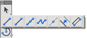
The subpalette appears to the right of the tool.
3. Drag the pointer to highlight the desired tool.
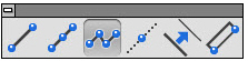
4. Release the mouse button.
The selected tool replaces the previous tool in the tool palette. The highlighted icon in the tool palette shows that the selection from the subpalette is the active or current tool.
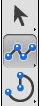
The new tool is visible in the tool palette until another tool is selected from the same subpalette. The tools in the subpalette remain in the same order; only the tool displayed on the tool palette changes.
Once a tool is selected, additional information appears to help with the construction. The Pointer, Pointer Locator, Message Line, and Status Line all provide feedback about the active tool.
To select a tool that is already displayed in the tool palette just click it. It is unnecessary to select it from the subpalette.
All tool palettes containing subpalettes are capable of tearing away from the parent palette. To tear away the subpalette from the parent tool palette click the small button in the upper right corner of the subpalette.

Move the subpalette anywhere in the drawing area. To save the palette in this location choose Layout>Preferences>Save Palette. Close the palette by double clicking on the left button in its title bar.
When selecting a tool and moving the pointer in the drawing area, the pointer shape represents the selected tool.
Some of the pointers, like the single line pointer, are simple cross-hairs. Others, such as the Opposite-Point Circle pointer, resemble the tool itself.
The pointer, called a smart pointer, displays indicators for multi-step procedures. Each smart pointer has a dot, the hot spot, showing the next point to specify. The dot changes position on the pointer during each step of the construction.
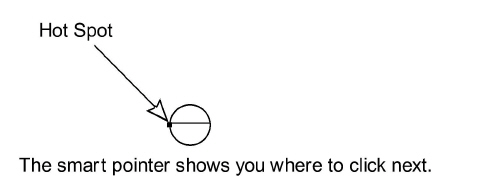
For example, the Opposite-Point Circle pointer illustrated above shows that the first click of the mouse places a point on one edge of the circle being created. After clicking a location, the hot spot moves to the other side of the pointer, showing that the next click places a point on the opposite edge of the circle. (See the graphic below).
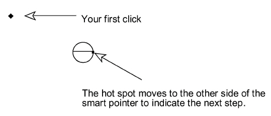
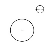
After clicking the second location, the circle appears. The hot spot moves back to its original position on the pointer so that another circle can be created.
The Pointer Locator is three numbers to the left of the horizontal scroll buttons at the bottom of the drawing area.
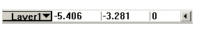
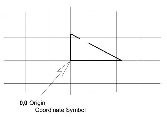
This locator continuously tracks the pointer location when the pointer is in the drawing area, displaying the X,Y coordinates of the current location relative to the origin. The origin (0,0,0) is in the center of the screen when a new document is opened. When making the grid visible by choosing Layout>Show Grid, a symbol appears at the origin (0,0).
Tech Note: The number of decimal places displayed in the locator field is determined by the Precision setting in the Units dialog box (choose Layout>Preferences>Units).
The location indicator tracks the pointer position of any tool other than the Selection tool.
The Message Line across the top of the drawing area provides concise instructions for the use of the selected tool.
For example, after selecting the Center-Point Circle tool, the Message Line appears as illustrated below:
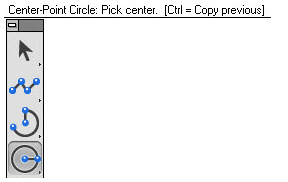
The instructions in the Message Line for some tools also indicate optional activities. For example, by holding down the CTRL (Windows) or OPTION (Macintosh) key while using the Center-Point Circle tool, the next mouse click creates a copy of the last circle with the center placed where the mouse was clicked.
The Status Line provides measurements, angles, X,Y coordinates and delta values for the current construction. The current tool determines the number of status data fields and which of the status data fields is highlighted after the construction. For example, if the Center-Point Circle tool is selected, the Status Line shows the X,Y, Z coordinates for the center of the circle and the length of the diameter.

When the last point of the circle is clicked, the diameter (D) data field highlights in the Status Line to indicate that it is active. It shows the diameter of the circle just created. If a new number is typed, and the ENTER (Windows) or RETURN (Macintosh) key is pressed, the diameter of the circle updates reflecting the change.
Entries can be changed in the Status Line, until the ENTER (Windows) or RETURN (Macintosh) is pressed.
The number of decimal places displayed in the status data fields is determined by the Precision setting in the Units dialog box (choose Layout>Preferences>Units).
Tip: Objects can be also changed with the Edit Objects command.
Moving Between Status Data Fields
Use the TAB key to move to the right, highlighting the next field. When pressing ENTER (Windows) or RETURN (Macintosh), the construction redraws according to the new specifications in the Status Line. The mouse is also used to activate a Status Line data field.
Use the Status Line arrows to scroll if any of the status data fields are off screen.
Use the drawing area for all construction, editing, and annotation of geometry. Think of the drawing area as a sheet of paper of unlimited size that is used to construct full-size unscaled drawings. Use the scroll bars to move the sheet so that the desired portion is visible in the window.
To work with a grid in the drawing area, choose Layout>Show Grid.
When the grid is visible, constructions snap to the grid, meaning that any geometry point clicked snaps onto the closest grid point. The coordinate symbol appears at the origin when the grid is visible.
Tip: Normally, it is not necessarily to display the Grid, since the Drafting Assistant offers a more elegant support than the grid.
The scroll bars move the sheet up and down or right and left. Display different parts of the drawing sheet by dragging the slider of a scroll bar to the approximate location. For example, the right, center, or left position in the horizontal scroll bar displays the right side, middle, or left side of the drawing, respectively.
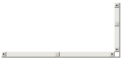
Click the arrows at the end of the scroll bars to move the sheet one line at a time. Click in the scroll bar to move the sheet one window at a time.
The work layer indicator in the lower-left corner of the screen shows which layer is the current work layer. New geometry goes on the work layer. For the construction to be on a specific layer, first make that the current layer.
To select a work layer, position the pointer over the work layer indicator, then press the mouse button. All available layers are then displayed in a pull-down menu from which a different layer can be selected as the current work layer.
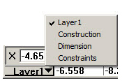
Drag to the layer and release the mouse button. The selected layer becomes the work layer and all geometry being created will be placed onto that layer.
Menu Bar, including the Dialog Boxes
The Graphite menus contain related commands and settings.
|
1. Point to the menu name.
2. Click on the name.
The menu appears. To dismiss the menu without making a choice, click outside the menu.
Choosing a Command from a Menu
1. Point to the menu name.
2. Click on the name.
The menu appears.
3. Click on the command.
The command executes, or the setting, such as Selectable Points, toggles on or off.
Graphite’s menu items are chosen with the mouse or with a combination of keys on the keyboard. For example, various methods are used for displaying the Edit menu.
• Click on Edit in the menu bar.
• Press the ALT key and then type E.
• Press the ALT key and then press the RIGHT ARROW key until Edit is highlighted in the menu bar; then press ENTER.
There are also various methods for choosing commands with the keyboard. For example, use any of the following methods to choose Layout>Show Grid.
• Press ALT and L and then type G.
• Press ALT and then use the RIGHT ARROW key to highlight Layout and press ENTER. Then press the DOWN ARROW key to move the highlighted area to Show Grid and press ENTER.
• Hold down the CTRL key and type G.
The first method is the mnemonic method. Press the ALT key with the appropriate letters for the menu and command as indicated by the underlined character in the names.
• Hold down the z COMMAND key and type G.
The third method for Windows, and the only one available for Macintosh, is a keyboard accelerator. When available it is denoted by the key sequence listed on the menu.
While keyboard functionality is always available, this manual generally describes making choices with the mouse.
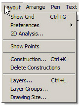
Commands followed by an arrow have submenus which display when the command is highlighted.
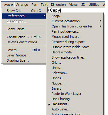
1. Pull down the menu.
2. Click on a command with an (arrow) on the end.
The submenu displays.
3. Click on the submenu.
When choosing a command followed by an ellipsis (…), such as Edit Objects in the Edit menu, a dialog box appears.
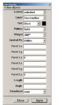
Dialog boxes qualify the command chosen by adding information. For example, in the Edit Objects dialog box on the right, the specifications of the selected object are changed.
If a dialog box obscures the view of the drawing area, move it to a new location by dragging it with the pointer on the Title bar.
Option buttons indicate mutually exclusive choices; select only one option at a time. Click the desired option and the button turns black, as shown by the inches option below.
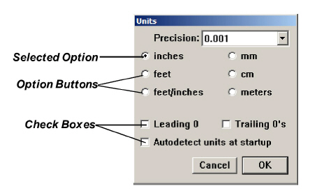
Check boxes, as shown above, provide options to switch on and off and which are not mutually exclusive. A check shows the option set.
Some dialog boxes contain lists of options, displaying an arrow to provide access to the list.
If the entry includes an arrow, it displays a menu which works like a submenu on the menu bar displaying the selected item in the box.
Some list boxes also allow an entry to be typed. For example, type a value in the Scale data field in the Drawing Size dialog box or choose from the pop-up menu. See the graphic below.
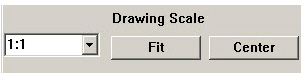
To type an entry, select the current entry (if it isn’t already selected), then type a new entry. In most cases, clicking on the OK button, saves the changes.
Tip: Windows: An alternative is to hold down the ALT key and type a letter to select the first item that begins with that letter, then use the arrow keys to move to the desired selection. Once it is highlighted, press ENTER.
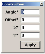
When an item in the dialog box displays an asterisk (*), a value can be specified by clicking or dragging in the drawing area. This feature is particularly useful for specifying location because knowing the x, y coordinates is not necessary.
Some dialog boxes have an Apply button so that the specification can be activated and left open for setting further specifications.
For example, crosshatch a part then leave the Crosshatch dialog box open to crosshatch other objects.
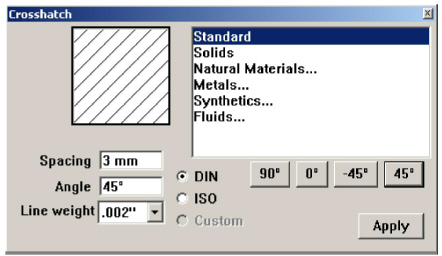
If a dialog box contains an OK or Cancel button or an action button such as Open, the dialog box closes after clicking the button. Otherwise, to dismiss the dialog box manually double-click the Control Menu (Windows) or click the Close Button (Macintosh) in the upper-left corner of the box. If the dialog box has an Apply button, such as the Crosshatch dialog box above, you must dismiss it manually.
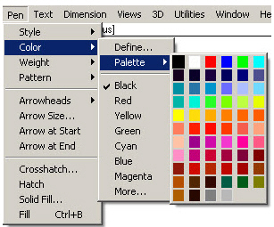
Commands that set a condition (such as Selectable Points and Arrow At Start) display a check mark in the menu to indicate that they are active. To turn a command off, choose it and the check mark disappears.
In the case of pen styles and text characteristics, the check shows the current setting.
Other commands, Show Grid, Show Points, Show Palette, Show Trackball and Show Triad toggle to Hide (Grid, Points, Palette, Trackball or Triad) when the component is visible.
All files are saved with their settings when choosing File>Save. The characteristics used for new files (the default settings) are contained in the preferences file. The preferences filename is prefs.vc6 (Windows) or Graphite prefs (Macintosh). Change the default settings so that every new document opens with the desired settings. The following specifications are set in the preferences file:
• Pen styles
• Text characteristics
• Preference settings (snap, grid, units, selection color indicator, visualization, palette status and palette location)
• Grid display
• Layer and sheet specifications
• Work layer
• Dimension and tolerance formats
• Arrowhead type and display
• Drawing size and scale
• Zoom scale
• Fillet radius
• Chamfer angle and length
• Resolve values
The default value of any setting that can be changed on a menu or in a dialog box can be set in the preferences file.
Changing the Default Settings Manually
1. Open the preferences file (it’s in the same folder as the Graphite application).
2. Change the characteristics and, if needed, create the layers and sheets.
3. Save and close the file.
The file must be stored in the same folder as the Graphite application.
The preferences are set for subsequent new documents.
The settings will not take effect until the next time you launch Graphite.
Changing the Default Settings with Save Preferences
1. Open a new Graphite file.
2. Set the preferences as needed.
3. Choose Layout>Preferences>Save Preferences.
The preferences are set for this file. The settings for future files take effect the next time you launch Graphite.
Important: It is advisable to use Save Preferences only before starting to draw. Otherwise, undesired data may be saved in new files. For example, if Save Preferences is chosen on a file with a detail view and multiple models, all new files will contain a detail view window and multiple models.
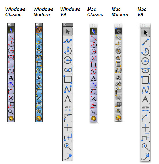
There are three different icon styles. V9 style is set by default. To use the Classic or Modern icon style instead choose: Layout>Preferences>Style>Classic.
To save the work window in desired size and position, choose Layout>Preferences>Save Work Window option.