


Graphite Overview
As mentioned in the Getting Started section of this manual, Graphite is a powerful program that is quick to learn and use due to its technology. Graphite helps you get the job done within your timeframe.
This chapter provides a brief overview of the following concepts:
In Graphite you create wireframe models. A wireframe model consists of the geometry that makes up the edges of the object.
A wireframe model is often used in place of a prototype so that simulations and tests are accomplished on the computer rather than in the laboratory. Models are used for checking the visual specification, measuring distances between points within the model and observing the visual and real intersections of lines.
3D wireframe models are most useful for showing multiple views and doing 2D dimensioning and drafting on those views. This lets you design in 3D, and then produce 2D working drawings from that 3D model.
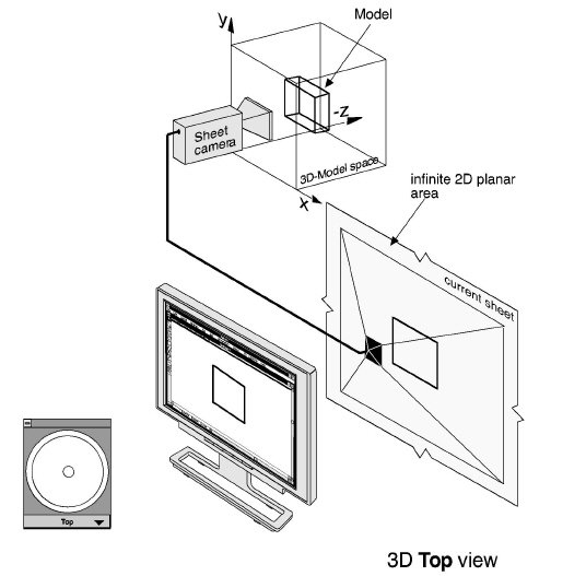
Models exist in 3D space in the computer’s memory, whether the geometry is two or three dimensional. A model is any combination of geometry, such as lines, arcs, circles, dimensions, text, etc. Models are created in an infinitely large three-dimensional area. (In the following graphics each model has its own imaginary 3D model space). Models are not created directly on the sheet. What you see on the sheet is only a projected view of the model.
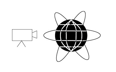
A sheet in Graphite is an infinite 2D planar area (always aligned parallel to the screen) that displays an image of one or more models. View the model as if looking through a camera while it moves around the model. The image of a model is picked up by either a sheet camera or a detail view camera. The sheet camera projects the image directly onto the sheet (called a Sheet View). The detail view camera projects the image into a view window (called a Detail View) which rests on the sheet. Sheets do not actually contain any geometry, only images of geometry.
Your computer screen displays all the views on the current sheet. In the graphic below a Top view of the model is picked up by the sheet camera and projected onto the current sheet. In the Top view the sheet camera is aligned parallel to the sheet.
Referral: The definition of models is also discussed in Advanced Viewing Techniques.
Opening a document, you are looking down on top of the x, y plane and you cannot see anything in the z-direction, which is coming toward you, away from the screen.
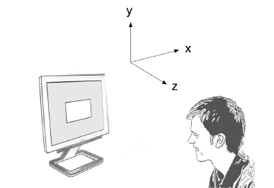
Rotate the image to see what you are drawing in the z-direction.
The on-screen Trackball rotates the sheet camera around the 3D model. This changes your orientation, it does not rotate the model. The three-dimensional object geometry (the model) stays fixed, even if the opposite impression is displayed on the screen.
In the following graphic the sheet camera is rotated to the Trimetric view.
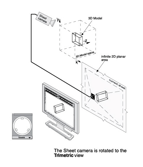
When rotating the image with the on-screen Trackball, it is as though the movement of the pointer on the Trackball corresponds to a fulcrum; the location where you press the mouse button becomes the fulcrum and the movement of the mouse rotates the model around that fulcrum point. What you see on the screen responds to the view of the sheet camera.
When creating view windows, either detail views, drafting layouts, or design layouts, each view window looks at the same model. When a change is made in any view window, the model changes; therefore, the model in every view changes.
For more information on models, see Advanced Viewing Techniques.
The Drafting Assistant is unique to Ashlar-Vellum software and makes Graphite easy to use because it thinks like a designer. The Drafting Assistant guides a designer in the creation of geometry. It displays temporary construction lines, provides information about existing geometry, and gives notations of the relationship between new and existing geometry in all three dimensions.
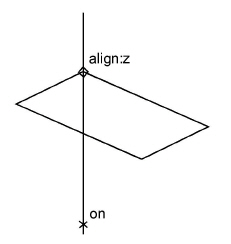
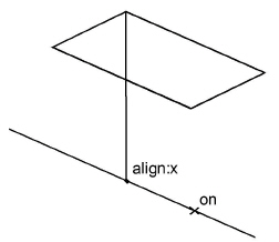
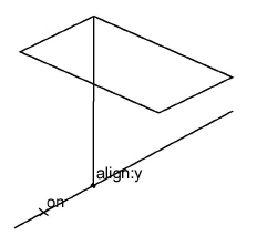
Move the pointer near an existing geometric construction and the Drafting Assistant’s snap point locks onto individual geometry, displaying an on notation. The Drafting Assistant also displays information about geometric landmarks, such as endpoints and centers, and temporary automatic construction lines, such as alignment and tangents.
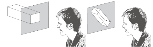
The following examples illustrate the alignment notations for the x, y and z axes.
|
For more information see The Drafting Assistant.
The computer revolutionized the design process. Graphite has contributed to this by allowing you to quickly design a model that previously existed only in your mind's eye.
Using Graphite it is possible to start designing immediately in 3D or begin in 2D and continue later in 3D.
For example, you can choose to begin designing in the Trimetric view orientation so that you see all three directions at once. Display other view windows with the Front, Right, and Top view orientations at quarter scale to observe the construction from other angles. While drawing, you can zoom in and out to enlarge and reduce areas as needed.
Rotate, move the origin, and change the work plane to take advantage of the 3D modeling environment.
In the paper world, a model design begins by deciding what scale to use so that the model fits on a particular size sheet of paper. With Graphite, scaling is postponed until after the model is drawn at full scale. Scale the geometry to fit on a standard drawing format provided by Graphite and then scale the whole drawing to fit the size of paper needed.
There are several different methods to create a model. The following steps are an example of a process for a 3D model:
• Begin the construction by opening a new document.
• Set the preferences you prefer, such as the pen style, grid, and selection modes.
For more information, see Basic Environment Settings
• Display the Triad symbol using the Show Triad command. This illustrates the work plane orientation that acts as a point of reference when drawing in 3D.
• In the view menu of the Trackball, choose Trimetric. The sheet rotates so that the construction is seen from the Trimetric view.
• Create the 3D model using the tool palette and Graphite commands.
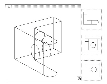
• To observe multiple view orientations while modeling, choose Sheet Into View from the Views menu, and then specify the Views Design 4 layout. View windows displaying the Top, Front, and Right view orientations are displayed at quarter scale along the right side of the screen.
For more information on Sheet into Views, see Advanced Viewing Techniques
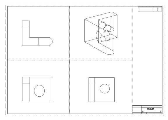
When the model is complete (or to be submitted for review), you might want a drafting version incorporating several views in a drawing format with dimensions and annotations. To create this, import a drawing format and make adjustments to the views as necessary or use a premade layout with format in Sheet Into View. This example shows a premade layout with four views.
• Flatten any view that contains geometry to be edited independently. For more information on flattening a view, see Advanced Viewing Techniques
• Crosshatch, dimension, annotate, and perform any view editing needed.
• Fine-tune the model if necessary.
• Specify the paper size from the Print Setup (Windows) or Page Setup (Macintosh) command in the File menu.
• Set the scale for the drawing format to fit on the plotter paper. If an exact scale is not necessary, click Fit in the Drawing Size dialog box and the geometry and format will be scaled appropriately for the paper size specified.
• Plot the finished drawing. For more information on plotting, printing and related activities, see Graphite Documents