


Sheets, views and models are features in Graphite that add a great amount of flexibility to the design process. This chapter explains each of them and how they interact with each other. The following topics are included:
• Sheets
• Models
• Views, Including Sheet into View and View Layouts
• Combining Sheets, Views and Models
A sheet is an infinite planar area. Graphite allows multiple opaque sheets within a drawing. A drawing can be a simple part or a complex assembly, with related geometry organized on as many sheets as the scope of the project demand.
There can be many sheets but only one sheet is active, and therefore, visible at a time. To activate a sheet use the Current command in the Sheets dialog box in the Views menu. In Graphite one sheet is always the active sheet which cannot be deleted.
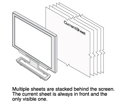
Having multiple sheets, imagine them arranged as a stack of sheets behind the computer screen. To make a sheet current bring it to the front. That is why only one sheet, the current sheet, can be seen at a time.
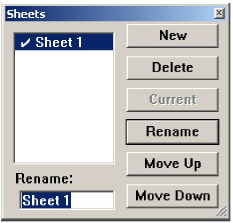
Every document contains Sheet 1. Use the Sheets command in the Views menu to create new sheets, delete, rename, or set the current work sheet. Give the sheets distinctive names, rather than their default numbers, because it is much easier to know what’s on a sheet if it's named, for instance, Detail View, rather than Sheet 2.
Sheets are Graphite’s equivalent to pieces of paper, with the added function that Sheet 2 can display geometry associated with Sheet 1. When using detail views, layers won’t serve your needs for printing or plotting. This is because when the layer containing the geometry that the detail view is associated with is hidden, the geometry is also no longer visible in the detail view.
Use sheets to display and print multiple pages of complex drawings. The following example explains the process:
• When opening a new document, Sheet 1 displays in the drawing area.
• Create a complex assembly and a detail view on Sheet 1.
• When it is time to plot the project, the assembly is found to fill all of the plotting area and there is no room for the detail view on the page.
• Select the detail view and choose Cut from the active View window menu (not from the Edit menu in the menu bar).
• Choose Views>Sheets and click New to create another sheet (Sheet 2).
• Click Current to make Sheet 2 the current sheet.
A blank sheet displays.
• Choose Edit>Paste to paste the detail view on Sheet 2.
The detail view displays on Sheet 2.
Use Zoom All in order to see the detail view.
Finally, check to see that the detail view is still associated with the original assembly:
• Make Sheet 1 current and make a change to the area of the assembly that is in the detail view. (Remember: Crosshatching, Text, and Dimensions are not associated in a detail view.)
• Look at Sheet 2 and see that the change appears in the detail view on Sheet 2 and, of course, changes made in the detail view are also be reflected in the Sheet 1 view.
Tip: To print a part related to one project separately, create a new sheet.
The Sheet command in the Views menu facilitates creating and naming sheets, and setting the work sheet. The check mark in the list of sheets indicates the current work sheet. The title bar for the document also indicates the active sheet (Document Name: Sheet Number). The name of the sheet only displays in the Title Bar if more than one sheet exists.
Use several sheets to create related components and associated detail views. Using a new sheet in Graphite is like using a fresh sheet of paper on a drafting board to create a component related to the larger project.
Click New to create another sheet. Name the sheet by typing the name in the Rename data field and clicking the Rename button.
Note: Graphite automatically creates a new model when creating a new sheet. See a later section for more information on models.
Tip: It is also possible to create a new sheet by typing a sheet name and then clicking New.
1. Select the name of the sheet from the list box.
2. Type the new name.
3. Click Rename.
1. Select the name of the sheet from the list box.
2. Click Delete.
Graphite handles Models and Sheets separately. The geometry created is the model. What you see on the sheet is only an image (view) of that model. So when the sheet is deleted only the Sheet View or Detail View of the model is deleted, but not the geometry (model) itself.
Note: The current sheet cannot be deleted.
1. Select the name from the list.
2. Click Current.
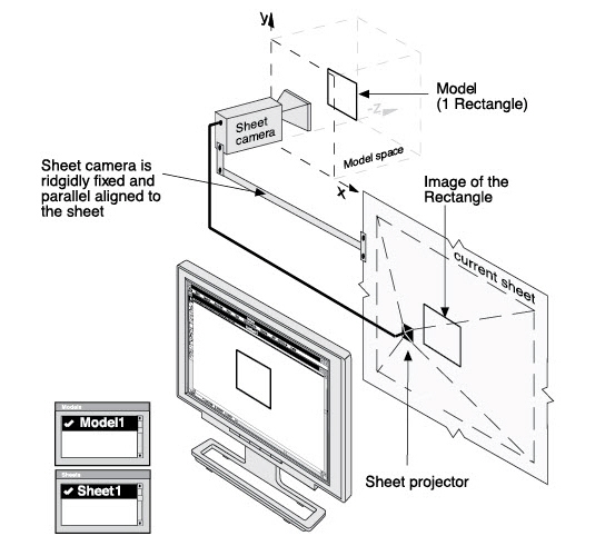
Models are composed of the geometry you create. Even if it looks like the geometry is created directly on the sheet, it is not. What is seen on the sheet is only an image of that model. The model itself is created in an infinite three-dimensional area we call Model space.
Tip: Any combination of geometry such as lines, arcs, circles, dimensions, text, etc. created using the tools in Graphite is a model.
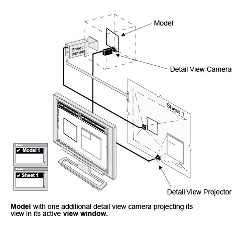
The image on the sheet is the projected sheet view of the model picked up by the sheet camera which is aligned parallel to the sheet and looking from a top view, at the model.
When the Zoom commands in the Arrange menu or the Zoom tools from the tool palette are used, it changes the view scale of the model by zooming the sheet camera like a video camera.
There are two different ways to create models:
• Using the Sheets command in the Views menu.
• With the Model command in the Views menu.
When creating a new sheet, Graphite automatically creates a new blank model where geometry can be created.
Tech Note: The Sheet Into View command also creates a new model for the sheet view. The existing model is placed in the detail view window. See a later section of this chapter for more information.
Creating a New Model with the Sheets Command
This task assumes that any additional models and sheets are not created.
1. Select Views>Sheets.
The Sheets dialog box displays.
2. Select Views>Models.
The Models dialog box displays.
3. Since the Model dialog box is placed at the same location on the screen, move it to another location to see both dialog boxes.
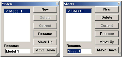
A new drawing in Graphite has one Sheet and one Model by default. The check mark in each dialog box shows that Sheet 1 and Model 1 are current.
4. Display the Sheets dialog box and click New to create a new sheet. A new model automatically appears in the Models dialog box (Model 2).
5. Make Sheet 2 current by highlighting it and clicking Current.
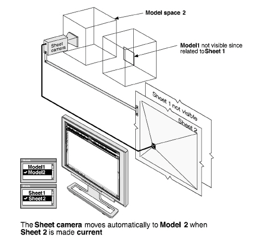
Any geometry on Sheet 1 disappears and a blank screen comes up. Also, the check mark moves from Sheet 1 to Sheet 2 and the check mark also moves automatically from Model 1 to Model 2.
Model 2 automatically becomes current because Sheet 2 is related to Model 2. So if you make Sheet 2 current on the screen, then Model 2 has to be current as well.
Sheet 2, now displayed on the monitor, is blank because nothing has yet been added to Model 2. As soon as the drawing is begun, all geometry automatically adds to Model 2 since Model 2 is the current model space.
Relationship between Sheets and Models
When a new model is created with the Model command, it is created without creating a new sheet. So it is possible to have more models than there are sheets. It is only possible to look at one model at a time in any view (sheet view or detail view) if the geometry is contained in different model spaces (i.e. Model 1 or Model 2). Think of models as a spatial area where geometry is located. Two spatial areas cannot be viewed through one window at the same time.
It is possible to create more models than there are view windows. It is also possible to have a model that is not displayed in any view. And a single model can be displayed in many views at the same time.
Making a model current in a sheet view is like moving the sheet camera moved to the new model. Making a sheet current, is like moving the sheet camera to the related model whose image is projected on that sheet.
The Models command in the Views menu specifies models and switches between models, projecting them on the current sheet. It is possible to display a single model on more than one sheet, but only one model can be viewed at a time on each sheet without using detail views.
Click New to create another model. Name the model by typing the name in the Rename data field and clicking Rename.
Tip: It is also possible to create a new model by typing a model name and then clicking New.
1. Select the name of the model from the list box.
2. Type the new name.
3. Click Rename.
1. Select the name of the model from the list box.
2. Click Delete.
When deleting a model, all of the geometry making up that model is deleted.
Note: The current model cannot be deleted. A model which is still associated with a sheet cannot be deleted. As long as it is related to a sheet the Delete button in the Models dialog box is not available.
Making a Model the Current Model
1. Activate the view (sheet view or detail view) by clicking on it.
2. Select the name from the list in the Models dialog box.
3. Click Current. A check mark shows the current model for the current view.
Generally, a model is created on a single sheet. When it is time to create drafting views of the model, it may be necessary to have several sheets because the model is so large or so detailed that it requires more than one sheet of paper for the finished drawing.
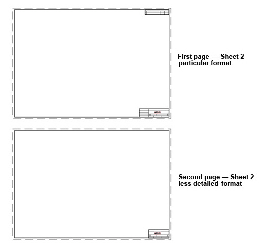
For example, designing a dental workstation, place the view on one page showing the chair, work tray, x-ray and drill arms.
Then on subsequent pages, add the detail views of the x-ray arm and drill setup. In addition to this, the first sheet would use a particular format and the following sheets would use a different, less detailed drawing format.
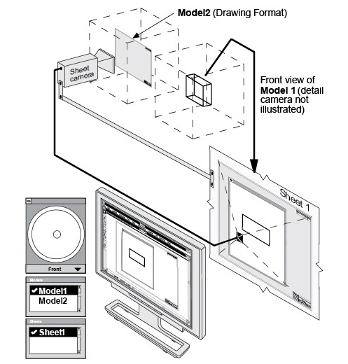
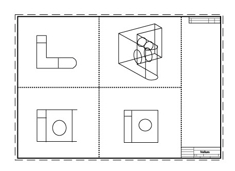
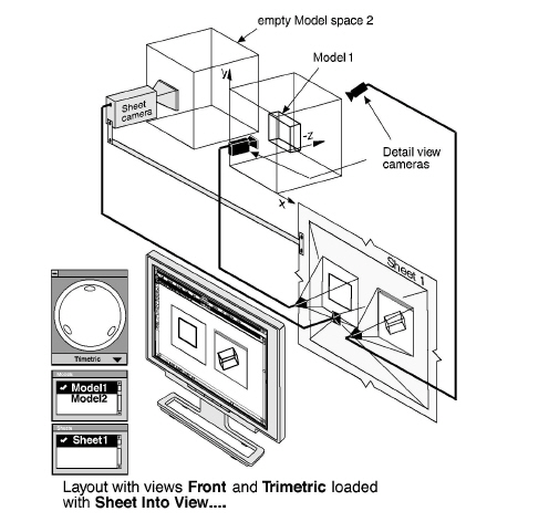
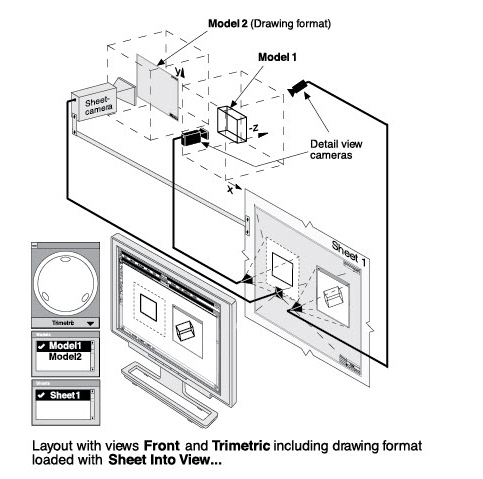
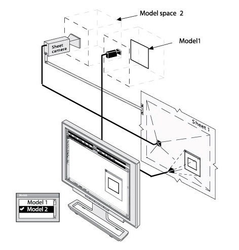
The key to using more than one sheet of paper is to use Graphite’s model and sheet functions. In the example below, start with the front view of a model (Model 1) on a drawing format (Model 2) on Sheet 1. Then open Sheet 2 and display all four views of Model 1 on it.
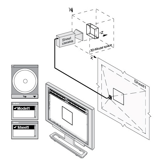
1. Create the part.
Model 1 contains the part and its Top view is picked up by the sheet camera and displayed on Sheet 1.
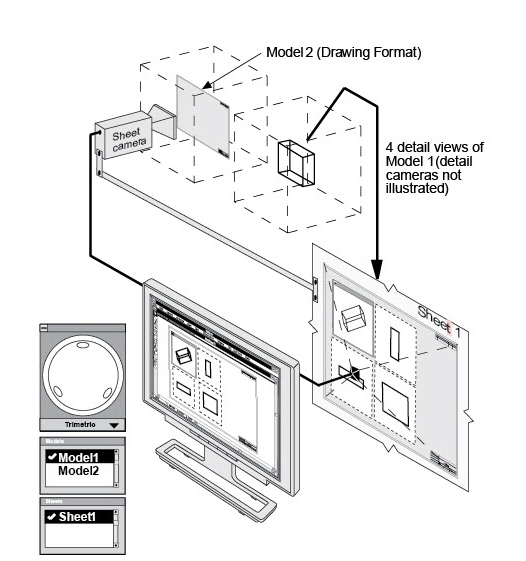
2. In the Views menu, use the Sheet Into View command to set up four views in the appropriate sized drawing format.
The sheet camera aligns parallel to the current sheet and displays the Top view of Model 2 (the drawing format) on Sheet 1. Four detail view cameras display 4 views of Model 1 on Sheet 1 within the drawing format.
3. Use the Cut command in the view window menu to remove all the view windows, except the Front view.
4. Resize the remaining Front view window so that it fills the drawing format
.
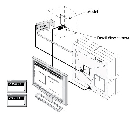
5. Choose Views>Sheets.
The Sheets dialog box displays.
6. Click New.
Sheet 2 displays in the Rename box.
7. Click Current.
Sheet 2 with the blank Model 3 displays in the drawing area.
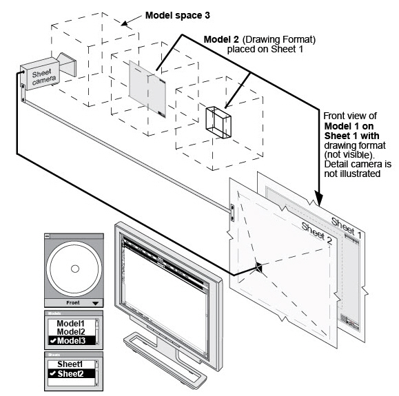
8. Choose Views>Models.
The Models dialog box displays. The blank Model 3 is the current model automatically created with Sheet 2, picked up by the sheet camera and displayed on Sheet 2.
9. Click Model 1 and click Current.
Model 1 is picked up by the sheet camera and displayed on the second sheet.
10. (Optional) Delete Model 3 since it is no longer needed. Model 3 was automatically created with Sheet 2.
Another possibility is to leave Model 3 active and paste the views of Model 1, which were removed with the Cut command at the beginning of this exercise, on Sheet 2.
11. Choose Views>Sheet Into View and select the appropriate format and views.
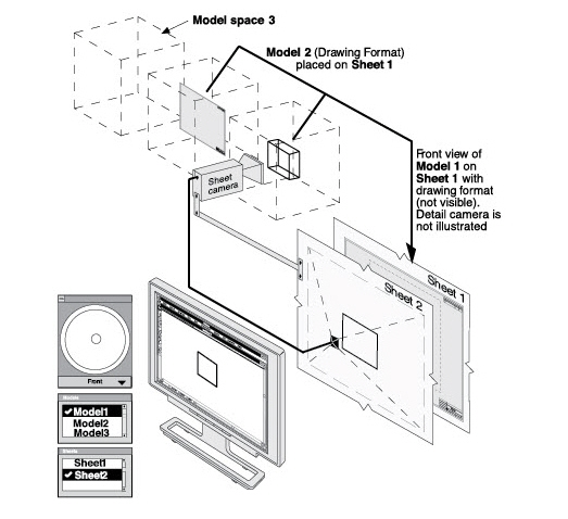
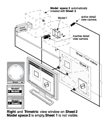
With the Sheet Into View command, place views from the current Model 1 on the current Sheet 2. The sheet camera moves to Model 3, which was automatically created with Sheet Into View and displays the appropriate drawing format on Sheet 2. Sheet 1 with the front view of Model 1 lies behind Sheet 2 and is not visible.
Note: The sheet camera is moved to Model 4 if Model 3 was not deleted in Step 10.
When Sheet 1 is made current, Sheet 1 moves forward and the sheet camera moves to Model 2 (drawing format) and displays the Front view of Model 1 within the drawing format, because Model 2 (drawing format) rests on Sheet 2.
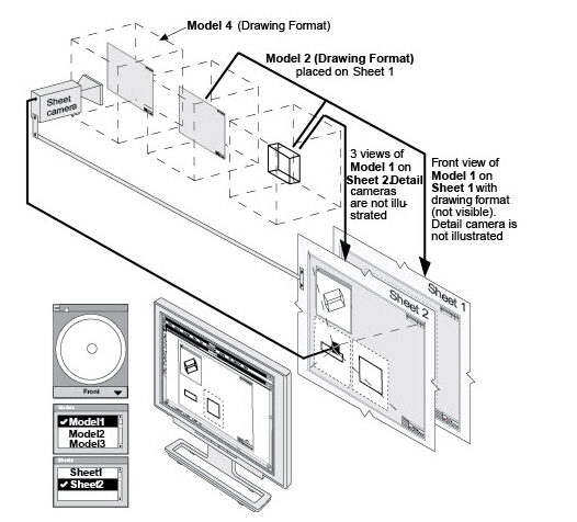
12. Arrange the views on the sheet.
Views, Including Sheet into View and View Layouts
In the previous chapter, the concepts of sheet views and detail views were discussed.
These two different views are easy to identify on the screen:
• Each item displayed inside a view window is a detail view.
• The area outside (and underneath) all detail view windows is the sheet view.
This section goes into greater detail on views and models, including Sheet into View.
Tech Note: Regardless of the method used to create a View Window, they all behave the same way. They all have a border which can be turned on and off in the Views menu with the Show/Hide View Boundaries command. The active view is displayed in a view window which has a title bar.
More about Associative Detail Views
When creating a detail view with the Detail View tool on the tool palette or the Sheet Into View command in the Views menu, the same model is viewed through a second camera—the detail view camera.
The detail view camera behaves like the sheet camera except it displays its view of the model in a view window on the sheet.
All views displaying the same model are associative. For example, when changing the geometry on the sheet, the geometry in the view window changes, and vice versa.
Having several views displaying the same model they have to be associative, because no matter which view is active—the sheet view or any detail view— the same model is being edited.
Tip: To move a view window to another sheet, cut the view window with the Cut command in the View Windows’s control menu, make the other sheet active and place the view window with the Paste command in the Edit menu on the current sheet.
To make a view active click on it. When clicking on the sheet, the sheet view becomes active. When clicking in a view window, the detail view becomes active.
When it is uncertain which view displays which model, open the Models dialog box. When clicking on the drawing area, the check mark moves to the model displayed on the sheet. Click in a view window and the check mark moves to the model displayed in the detail view.
Tip: This procedure is very useful to identify models and sheets for renaming.
Zooming affects the sheet view and the detail view differently. Zooming in a detail view with the SHIFT (Windows) or the CONTROL (Macintosh) key pressed, changes the view scale property of that view only. With the Zoom or Stroke-Zoom commands, it is possible to change only the screen display scale of the sheet and all detail views projected on that sheet, but not the size of the geometry itself.
Tip: Change the scale of a detail view with the Properties command in the view window’s Control menu.
Text, Dimensions, Crosshatching, Fills and Detail Views
While it is important that changes made to geometry in one view be reflected in the other views, the same is not true for text, dimensions, crosshatching and fills. The views become very cluttered and are rendered useless if all notations made in one view appear in the others. For that reason, Ashlar-Vellum designed these elements so that they would not be associative, in line with standard drafting practice.
The Sheet Into View command places all the geometry on a sheet, including dimensions, text, crosshatching, and fills, into one view window (the front).
The view window created with the Sheet Into View command behaves like any view window created with the Detail View tool. Although both view windows behave the same, the Sheet Into View command includes three automatic steps which are not performed when a view window is created with the Detail View tool.
The Sheet Into View command:
• Creates an additional model (blank or containing a standard drawing format if selected).
• Moves the sheet camera to that model (blank or with the drawing format) to display it on the current sheet.
Tip: Documents are more manageable if all existing view windows are deleted before using the Sheet Into View command.
• Puts all geometry, including text, dimensions, crosshatching, and fills on the current sheet into a view window and displays it in the scale specified within the selected drawing format.
.
Tip: Use the Sheet Into View command when importing a drawing format which is a different scale from the geometry.
Placing Geometry into a View Using Sheet into View
1. Draw the geometry.
2. Choose Views>Sheet Into View.
3. Choose the layout from the Layout menu. It is possible to choose from a view with no drawing format or a view in a standard drawing format.
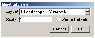
4. Enter the scaling value in the Scale box if you need a certain value, or just check the Zoom Extents option to make the drawing fit into the view window. Factors greater than one enlarge the model in the view(s) and factors less than one reduce the model.
5. Click OK.
6. Choose Arrange>Zoom All.
The geometry scales and the views appear as specified. By specifying a drawing format, it imports into the view and scales appropriately for the specified drawing size.
Tip: Add your own formats to this list as described in Graphite Documents, or modify the layouts provided to meet your needs.
Adding Formats to the Sheet Into View Dialog Box List
To create the drawing formats and add them to the list in the Sheet into View dialog box do the following:
1. Start a new document.
2. Select the Detail View tool and create a view window.
3. Display the Models dialog box and create a new model.
4. Click on the sheet and make Model 2 the current model in the Model dialog box.
5. Click in the view window and make Model 1 the current model in the Models dialog box.
6. Click on the sheet to activate Model 2.
7. Create the drawing format at a scale 1:1 or import one of Ashlar-Vellum formats and modify it.
8. Save the drawing with a proper name in the Layouts folder of Graphite.
The Filename is listed on the Layout menu.
See Graphite Documents, for more information on formats and customizing.
Tip: It is also possible to open one of the layouts in the Layouts folder of Graphite and change it. But be sure to save that layout under a different name before modifying it.
Having mistakenly invoked the Sheet Into View command, use Undo to recover. If this is not done immediately, use the following method to manually back out.
Recovering from an Erroneous Sheet Into View
1. Delete all view windows on the current sheet by choosing Delete from the view window’s Control menu of each view.
2. Make Model 1 in the Model dialog box the current model for the Sheet View.
3. Delete Model 2.
There are many options for changing the view orientation within the view window.
• Rotate the view with the Trackball.
• Choose 3D>Views and select a view.
• Select a view from the pull-down menu on the Trackball.
• Set a view with the Define View command.
• Unfold a view with the Unfold View command.
• Set the view to the current work plane with the View the Plane command.
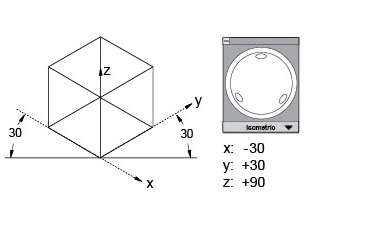
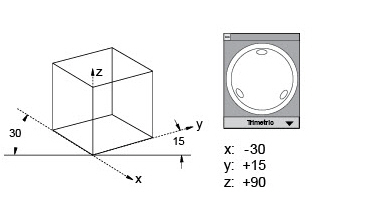
The Define View command in the Views menu defines an auxiliary view orientation or changes the standard view orientations. The standard views cannot be changed unless the locked check box is clicked off. The default configurations are defined as follows:
|
Follow these directions to specify a new view orientation.
1. Choose Views>Define View.
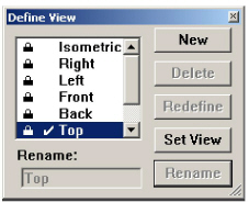
The Define View dialog box displays.
2. Click New.
The new work view is named View 1.
The Redefine View dialog box displays the locations for the current view. If that view is the desired view, click OK. Otherwise, proceed with the specification. The Normal (line of sight) specification highlights in the dialog box
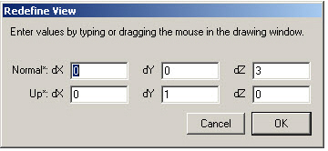
.
3. Drag a line in the active view window to indicate the Normal (line of sight) vector.
The Up data field becomes selected.
4. Drag a line in the active view window indicating the Up direction.
5. Click OK.
The dialog box closes and the new view is defined.
6. Click Set View.
The active view displays the new orientation.
7. Rename this view to give it a more distinctive name.
8. Close the Define View dialog box if there is no other need to define additional work views.
Be aware that simply rotating the view does not alter the orientation of the work plane in 3D space.
Select the view orientation to be deleted from the View list and click the Delete button.
There are two methods to change the orientation of the axes of a view.
1. Manipulate the view orientation manually with the Trackball.
2. Choose Views>Define View.
3. Select the view to redefine.
4. Click Redefine.
5. Click OK.
The Redefine View dialog box closes.
6. Dismiss the Define View dialog box if there is no other need for it.
1. Choose Views>Define View.
2. Select the view to redefine.
3. Click Redefine.
The Redefine View dialog box displays the settings as they appear on the screen with Normal (line of sight) selected.
4. In the active view window, drag the Normal (line of sight).
The Up data field becomes selected.
5. Drag the direction for up.
When dragging the normal vector with the mouse, know that the vector, from the beginning point, points directly at you, not away from you. So when this new view is made current, the normal vector points out of the screen, not into it.
6. Click OK.
The Redefine View dialog box closes.
7. Dismiss the Define View dialog box if it is not needed.
1. Click the view orientation to be renamed.
2. Type a new name.
3. Click Rename.
Renaming a Standard View Orientation
1. Click the standard view name in the list box.
2. Click the Locked box to toggle it off.
3. Type a new name.
4. Click Rename.
The Unfold View command in the Views menu creates a view orientation from the active view window by specifying a line from which to unfold the new view orientation.
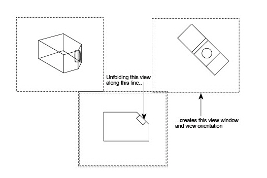
By specifying a line a 90°-plane along that line, which is coming towards you away from the screen. This plane is folded by 90° and creates the new view orientation from the active view.
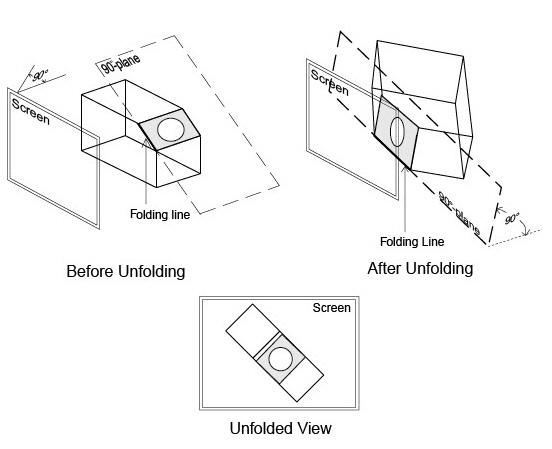
Note: Use this command only in a view orientation aligned parallel to an object face. When using it in a differently aligned view (where object face is not parallel to the screen) this command may work correctly, but the result is unpredictable in most cases.
1. Choose Views>Unfold View.
2. Click the endpoints of the line on which to unfold.
An actual line is not necessary, just indicate a vector.
The active view window shows the view unfolded 90° from the line specified.
Setting the Screen to the Work Plane
Change the point of view to look directly at the work plane. Choose Views>View the Plane to do this.
This command in the Views menu rotates the view orientation in the active view window to match the work plane. The view changes so the work plane becomes horizontal on the screen. The y-direction of the work plane becomes vertical, and the z-direction of the work plane becomes the line of sight, coming directly out of the screen.
To leave this view orientation, select a view from the Trackball pull-down menu or the Views submenu, or use the Trackball for free rotation.
Editing a View Without Editing the Model
The geometry within view windows is associative. Making a change in one window, the change affects the model and therefore the geometry in all views. In the drafting phase of the design process, it is possible to edit the geometry in one view window without making the same changes to the model. For example, it might be necessary to clarify the view by removing a line or adding an arc visually, but not unnecessary make the actual change in the model.
Accomplished this by using the Flatten View command on the Views menu. When flattening a view, the geometry is taken out of the view and placed back on the sheet, where it is no longer associated with the model. In this way, it is possible to make changes to the geometry without changing the model or other views.
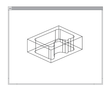
A typical situation for flattening a view is when a view should display fillets but the fillets do not need to be displayed in the model.
Trimming such intersecting fillets in 3D is a difficult problem that was addressed in the Getting Started Guide, but Graphite makes this problem very easy to solve.
The Flatten View command in the Views menu places a projection of the visible geometry in the active view window onto the sheet at full scale. When the view is flattened, all overlapping lines of equal length and all lines parallel to the line of sight are removed. The geometry is no longer associated with the model. If changes are made to the flattened geometry, those changes do not affect the model. If changes are made to the model, the flattened geometry is not changed.
1. Select a view window to make it the active view.
2. Choose Views>Flatten View.
A dialog box displays a warning message. Since flattening disassociates the current view from the model, be certain that this is not only the correct view to flatten, but also that it really should be flattened. All dimensions in the view are deleted because the 3D dimensions are not correct in 2D geometry.
3. Click OK. The geometry is placed on the sheet at full scale.
Important:
• The geometry is flattened at the scale being viewed. This scale is listed in the Control menu of the detail view.
• Text and crosshatching are treated like geometry by this command.
• Dimensions no longer update if a change is made to the 3D model since the flattened geometry is disassociated, but they change if the flattened geometry is altered. Also if the geometry is dimensioned after it is flattened, the desired values must be entered manually because Graphite simply reads the length of the projected flat lines. To keep the dimensions, copy the view and flatten the copy, or group the geometry with the dimensions, then flatten the view.
• If the following message appears, The current view and the draft view have the same model, it is necessary to change the model on the sheet. Click the sheet, outside all views, then choose Views>Models. Click New and then click Current. Repeat the above steps to flatten the view.
Included with Graphite are layouts set up with various views that can be chosen using the Sheet Into View command in the Views menu. It is also possible to create your own view layouts. In all but the Design.vc6, each view has the same scale. In the Design.vc6 layout, the Trimetric view is scaled as specified in the Sheet Into View dialog box and the other three views are scaled to 25% of the Trimetric view.
The default layouts available from the Sheet Into View command are as follows:
This layout shows the Top view of geometry, just as it is seen in 2D.
Views with Standard Drawing Formats
A Landscape 4 VIEW.vc6 (Windows & Macintosh); = 4 views for an A size sheet
B Landscape 4 VIEW.vc6 (Windows & Macintosh); = 4 views for a B size sheet
C Landscape 4 VIEW.vc6 (Windows & Macintosh); = 4 views for a C size sheet
D Landscape 4 VIEW.vc6 (Windows & Macintosh); = 4 views for a D size sheet
Design.vc6 (Windows); Views Design 4 (Macintosh)
This layout creates a Trimetric view at full scale and Top, Front, and Right views at 1/4 scale.
The design layout is primarily for viewing the model while designing it. When choosing this layout it may be desirable to change the scale and rearrange the smaller views to prepare for plotting.
Draft.vc6 (Windows); Views Draft 4 (Macintosh)
This layout creates four full-scale views: Top, Front, Right, and Trimetric.
This layout is a single Trimetric view at full scale.
Frntrit.vc6 (Windows); Views Front and Right (Macintosh)
This layout displays two full-scale views, the Front and Right.
Views Top and Front (Macintosh)
This layout displays two full-scale views, the Top and Front.
The specifications for the view layouts available from the Sheet Into View dialog box are in individual Graphite drawing files stored in the Layouts folder in the Graphite folder. To create your own layout or a customized drawing format, simply edit one of the existing drawings in the Layouts folder, or create a new drawing and save it in the Layouts folder. The filename will then appear in the pull-down menu in the Sheet Into View dialog box.
1. Choose File>Open and open a Layout file in the Layout folder.
2. Save the file under a different name in the Layout folder by choosing File>Save As before doing any changes.
3. Customize the layout as needed.
4. Save the file.
5. Select Views>Sheet Into View.
6. The new layout appears in the pull-down menu in the Sheet Into View dialog box.
Another way to create own layout is to design it in a new document.
1. Open a new document by choosing File>New.
2. Create a view window with the Detail View function.
3. Make the current sheet active by clicking anywhere outside the view window on the sheet.
4. Choose Views>Model and create Model 2.
5. Make Model 2 the current model in the Models dialog box.
6. Duplicate the view window as often as needed.
Duplicating or copying a view was discussed in Chapter 13.
7. Set each view window to the desired view orientation with the on-screen Trackball pull-down menu or the Views submenu in the Views menu.
8. Select Properties in the detail view window’s control menu to scale each view window.
9. Save the new layout under a proper name in the Layout folder of the Graphite folder.
Tip: Look at one of the files in the Layouts folder to see how it is set up. Be sure not to make any unwanted changes to these layout files.
Drafting Methods with Views and View Layouts
Two different methods exist for creating 3D wireframe models:
• Start the model creation on the drawing sheet and add views later for editing and viewing the model from different angles.
• Use a view layout from the beginning and create the model in different view windows simultaneously.
Open a document and create the geometry on an empty sheet. With the on-screen Trackball and the view commands in the View submenu, rotate the model and edit it from different angles as long as any detail view windows have not been created.
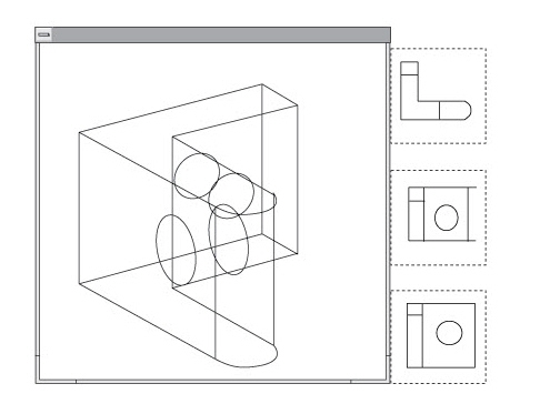
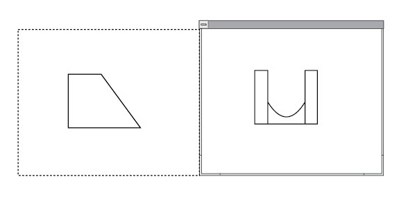
To view the geometry from different angles simultaneously, create detail view windows with the Detail View tool and place them on the sheet. The sheet view then shows an image of the model in the Top view on the sheet. In the view windows, display different view orientations of the geometry, like front, top, trimetric, etc.
As soon as a view window is created, the sheet view of the geometry remains fixed in the Top view parallel aligned and rigidly fixed to the sheet. As a result the view angle can only be changed in the detail view windows.
The view orientation of a sheet with a detail view cannot be rotated with the Trackball.
The sheet view of the geometry may overlap the view windows on the sheet as shown in the upper graphic. Create a new sheet with the Sheets dialog box in the View menu and Cut and Paste the view window from Sheet 1 onto Sheet 2 to get a clear view on the view windows.
Something similar, but more elegant, is done by the Sheet Into View command in the Views menu. Sheet Into View puts Model 1 into one or more views and puts Model 2 on the current sheet.
With this method choose a view layout with the Sheet Into View command. The views provide a vantage point of the model. It places all geometry into one of the view layouts. It is possible to customize the view layouts.
Sheet into View puts Model 1 into one or more views as specified by the choice from the dialog box and creates Model 2 and projects it onto the current sheet.
• By choosing one of the layouts that contain a title block and a border format, that format becomes Model 2 and is projected by the Sheet camera in the Top view on the current sheet.
Combining Sheets, Views and Models
In general, a powerful CAD program is necessary for two tasks:
• The creation of the designs.
• The generation of 2D engineering drawings, or blueprints, in order to get the designs built.
The design phase is effortless and very productive with the help of Graphite's Drafting Assistant, integrated parametrics (Parametrics), and the intuitive user interface itself.
For the second of these two tasks, very powerful and flexible drafting functions are desired, since there are so many possible types of drawings that might need to be created. One of the specific features in Graphite that handles this so well is the combined power of sheets, views and models.
For most daily work, it is not necessary to know anything about the relationship between sheets, views and models. But for some tasks it is helpful to understand this relationship since it offers elegant solutions that were not possible without the combined power of the features in Graphite.
The relationship between sheets, views and models makes it easy to:
• Place part views in different scales, such as 1:50, in a standard drawing format with a title block and borders that must be plotted at a scale of 1:1.
• Create detail views if an object that are not associative to the original model.
• Create customized drafting layouts.
• Recover from an erroneous Sheet into View command.
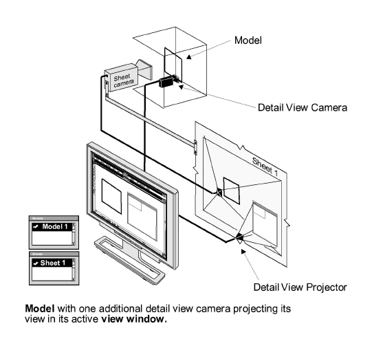
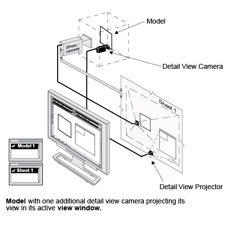
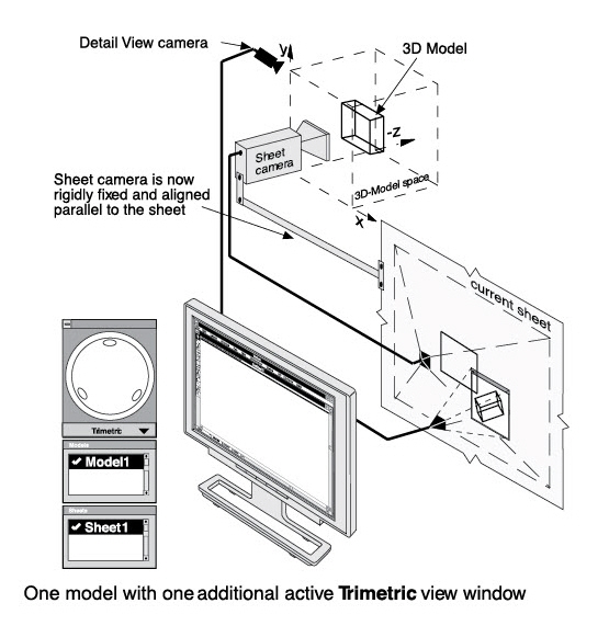
The first section of this chapter explained the use of sheets, views and models. Each is a simple and straight forward operation. In the graphics are shown the environment, and how sheets, views, and models are set up in Graphite. It is necessary to know the exact definition of all engaged components and the rules that describe how they interact.
The environment in Graphite for handling all geometry created can be described by five components—sheets, models, views, cameras, and projectors.
First, all geometry created is not created directly on the sheet on the computer screen but somewhere outside of the sheet in an infinitely large three-dimensional work space (Model space). All geometry is placed here as separate models. Only images or views of these models display on the sheet.
A sheet is an infinite 2D planar area that displays an image of one or more models. The image of a model is picked up either by the Sheet camera and projected onto the sheet (the Sheet View) or by a Detail View camera and projected into a view window which is resting on the sheet (the Detail View).
• Sheets are arranged behind each other so only one at a time can be seen.
• Create as many sheets as desired, but with each sheet a blank model is automatically created, similar to the drafting board when starting with a clean sheet.
• Independent of how many models exist, it is possible to delete all sheets but one—the current sheet—since Graphite needs at least one sheet to display the models even if they are blank.
• When deleting a sheet, all Detail Views resting on that sheet are deleted.
• Display as many Detail Views on one sheet as needed but only one sheet (Sheet View) at a time.
• When changing the current sheet, the related model is always activated. Change this relation only by assigning another model to that sheet.
A model is a collection of geometry, dimensions, text, fills and hatching. Models are placed in an infinite three-dimensional area. A model can be blank (then we call it Model space) just as it is when launching Graphite and looking at a blank sheet. Images of models are picked up by either the Sheet camera or by Detail View cameras and projected on the sheet. The view of the Sheet camera is called a Sheet View and the views of the detail cameras are called Detail Views.
• Create and delete as many models as desired.
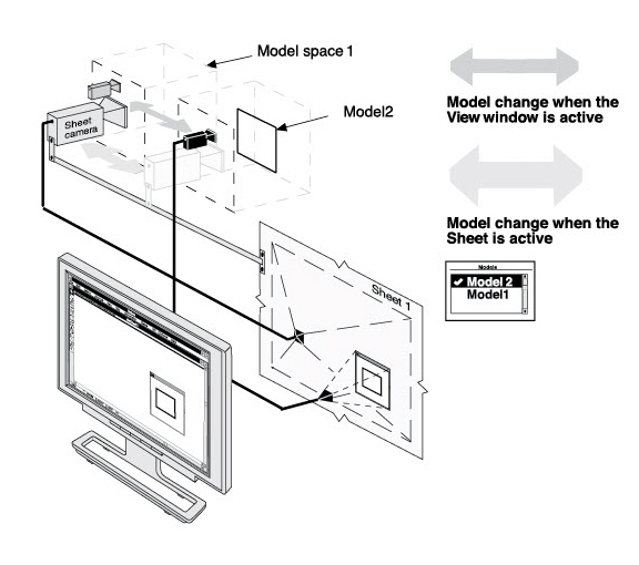
• When changing the current model, move the related camera. The camera you move depends on what is active—the sheet or the detail view. If the sheet is active, the Sheet camera moves to the current model. If the detail view is active then the related Detail view camera moves.
Views are the images picked up by cameras and projected on sheets. Graphite has two types of views—the Detail View and the Sheet View.
• Detail Views are picked up by Detail View cameras and always displayed in a view window which rests on the sheet. They have boundaries and display only a limited view of the model.
Create as many views as necessary and move or copy and paste them to different sheets.
When deleting a detail view, the Detail View Camera deletes. When deleting a sheet which contains a detail view, the detail view deletes also since the detail view rests on the sheet.
• Place views from different models on one sheet, but each view can display only one model at a time.
• Once a detail view is created, the sheet camera remains stationary in the original x,y (world) orientation. The view of the sheet can not be changed.
• There is only one sheet view for each sheet. The sheet view is an infinite view picked up by the Sheet camera and displays everything on the sheet outside of all view windows.
The sheet view cannot be deleted and needs at least one sheet to display its view.
Since the sheet view, like the detail view, can display only one model at a time, use detail views to show more than one model on a sheet.
• To activate a detail view click in the view window; to activate the sheet view click on the sheet outside of all detail views. If the Models dialog box is displayed, the related model is highlighted.
• The view orientation of a sheet becomes fixed when a detail view is created. The sheet camera remains stationary in the original x,y (world) orientation. The view of the sheet cannot be changed.
Tech Note: The Drawing Size command changes only the plot scale but not the scale factor of the Sheet view. Even if the view is scaled to fit the paper format the scale factor remains 1:1 since the real size of the geometry is not affected.
There are two type of cameras—one Sheet camera and as many Detail View cameras as detail views created.
• The Sheet camera is permanently installed as default and displays its view via the sheet projector on the sheet.
To move the Sheet camera perform a model change either by the Models command or by the Sheets command in which the Sheet camera moves automatically to the related model.
• Detail View cameras display their views via Detail View projectors in view windows which rest on the sheet.
Install as many Detail cameras as desired even if each one is looking at one model. Install Detail cameras by creating Detail views either by the Detail View tool from the tool palette or with the Sheet Into View command.
Move Detail View cameras to another model by performing a model change when the view window is active.
• Both cameras, the Sheet camera and a Detail View camera, can look at only one model at a time.
Tech Note: When changing the sheet, the Sheet camera is moved to the selected sheet and automatically displays it at the view scale which was current when the sheet was last changed.
Using Sheets, Views and Models
We listed many rules in the sections above and they all describe the same fact that Graphite administers geometry (models), views and sheets separately. That has a lot of advantages. The most impressive example is if you delete a sheet displaying geometry. The geometry is not lost since the related model is not deleted.
Practice the following examples and implement them in daily work. Using Models, Sheets and Views will become second nature and you will never want to work without them.
Recovering from Deleting a Sheet Displaying Geometry
To restore the geometry displayed on a sheet deleted unintentionally, proceed as follows:
1. Select Views>Sheets.
2. Click New to create a new sheet.
3. Click Current to activate the new sheet and draw some geometry.
4. Make another sheet active by highlighting a different sheet in the Sheets dialog box and click Current.
5. Close the Sheets dialog box and select Views>Models.
6. Search for the before-displayed geometry by activating each Model followed by a Zoom All command until the previous geometry displays on the new sheet.
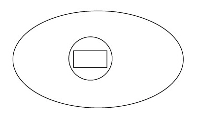
Displaying Three Components on One Sheet
Sheets, Views and Models are very helpful to display several components of a part created by different drafters on one sheet. The following simple example shows how to perform this task:
1. Open a new document.
2. Draw an ellipse.
3. Save the drawing as ellipse.vc6.
4. Open a new document and draw a rectangle.
5. Select Views>Sheet Into View.
6. In that dialog box, choose the ViewTop layout, set the Scale to 1 and click OK.
Now one Sheet is with one view window showing the Rectangle (Model 1). The Sheet camera aligns to Model 2 (created with the Sheet Into View command) displaying a blank model space on the sheet.
7. Make the sheet active by clicking on it and draw a circle.
8. Select Sheet Into View (the sheet still active) and choose Top view again with the Scale factor 1.
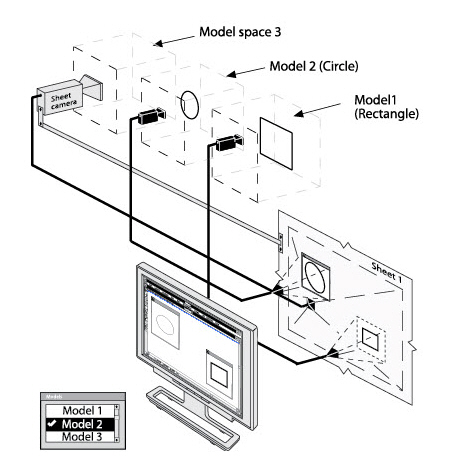
Now one Sheet has two view windows, one displaying the rectangle (Model 1) and one displaying the circle which became Model 2. The Sheet camera moves to the new Model 3 and an empty model space is displayed on the sheet.
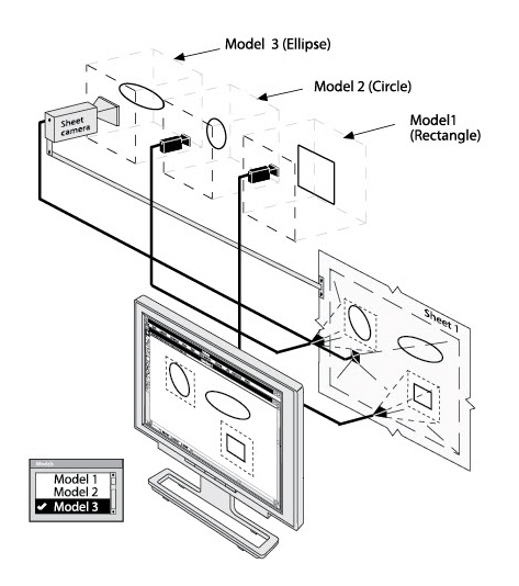
9. Activate the sheet by clicking on it and select File>Import.
10. Select the file ellipse.vc6 and click OK.
The ellipse imports onto the current sheet and is added to Model 3 which was active when the Import command was performed.
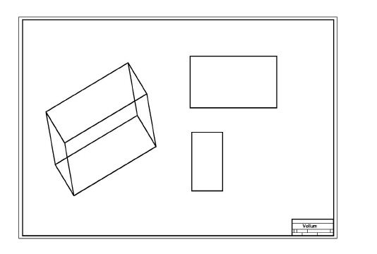
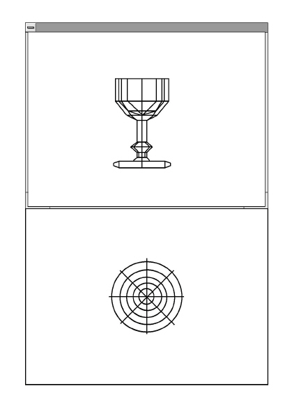
11. Arrange the two view windows around the ellipse and rearrange the rectangle and the circle with the Zoom commands in the Arrange menu like in the following graphic.
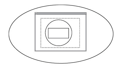
12. Activate the sheet and in the Views menu deactivate the Show View Boundaries command.
Tech Note: In order to select overlapping view windows, Auto Front must be deactivated, as described in Viewing Geometry